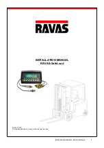
Ravas SafeLoad, Installation Manual
The Ravas SafeLoad product comes with an Installation Manual for easy setup. You can download the manual for free from manualshive.com to ensure safe operations. This comprehensive guide will help you make the most out of your Ravas SafeLoad experience.
Share
Download


Reviews:
No comments
Related manuals for SafeLoad
R55
Brand: RANKO Pages: 67

1100
Brand: Ravas Pages: 14
XC Series
Brand: HANGCHA Pages: 95
D35S-2
Brand: Daewoo Pages: 172
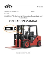
XF Series
Brand: HANGCHA Pages: 73
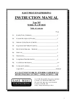
WP
Brand: East West Engineering Pages: 11

Bendi B40i4
Brand: Landoll Pages: 142
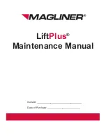
LiftPlus
Brand: Magliner Pages: 40
6145
Brand: VALLEY CRAFT Pages: 8

782008-R3
Brand: cascade corporation Pages: 12

H170FT
Brand: Hyster Pages: 21

SPM1516
Brand: Noblelift Pages: 8
PDH
Brand: Big Joe Pages: 28
FRSB14-8
Brand: UniCarriers Pages: 136

EPS14Pi
Brand: BYD Pages: 39

FD160-2
Brand: UniCarriers Pages: 158

ESC 316
Brand: Jungheinrich Pages: 157
WLX Series
Brand: UniCarriers Pages: 70


