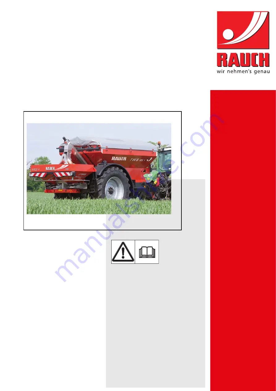
background image

INSTRUCTION MANUAL

TWS

85.1 

Please read carefully 
before using the ma-
chine.

Keep for future reference.

This instruction manual/assembly in-
struction is to be considered as part of
the machine. Suppliers of new and sec-
ond-hand machines are required to
document in writing that the instruc-
tion manual/assembly instruction was
delivered with the machine and hand-
ed over to the customer.

Original instructions

5901746-

a

-en-1015

Summary of Contents for TWS 85.1

Page 1: ...uction manual assembly in struction is to be considered as part of the machine Suppliers of new and sec ond hand machines are required to document in writing that the instruc tion manual assembly inst...

Page 2: ...ne Please note that damage caused by incorrect operation or improper use is not covered by war ranty claims Technical improvements We are continuously improving our products Therefore we reserve the r...

Page 3: ...n 7 3 4 3 Accident prevention 8 3 5 Information on operational safety 8 3 5 1 Unhitching and parking the machine 8 3 5 2 Filling the machine 9 3 5 3 Checks before start up 9 3 5 4 Hazard zone 10 3 5 5...

Page 4: ...aulic drive of the fertiliser spreader 36 6 5 Mount the universal drive shaft to the machine TWS M only 37 6 6 Connecting the machine to the tractor 38 6 6 1 Ball coupling 41 6 6 2 Pin coupling 41 6 6...

Page 5: ...e plan 74 9 2 1 General maintenance plan 74 9 2 2 Maintenance plan for axles and braking system 74 9 2 3 Maintenance plan for hydraulic system 75 9 3 Cleaning 75 9 4 Opening the protective grid 75 9 5...

Page 6: ...Table of Contents IV 10 Disposal 93 10 1 Safety 93 10 2 Disposal 94 Index A Terms conditions of warranty...

Page 7: ...rer For replacement purposes only original spare parts by the manufacturer may be used The load transfer vehicle TWS 85 1 may only be used maintained and repaired by people who are familiar with the c...

Page 8: ...enfabrik GmbH Landstrasse 14 76547 Sinzheim Germany We hereby declare that the product Load transfer vehicle TWS 85 1 complies with all relevant regulations of the EC Machinery Directive 2006 42 EC Te...

Page 9: ...ew owner The operator s manual is intended for the operator of the machine and anyone involved in operating and maintaining it It must be read understood and applied by all persons entrusted with the...

Page 10: ...ront of these instructions Handling instruction 2 3 2 Listings Listings without a specific sequence are shown with bullet points level 1 and dashes level 2 Property A Point A Point B Property B 2 3 3...

Page 11: ...ponents can be found in the respective sup plier documentation These warning instructions must also be observed 3 2 Significance of warnings The warning instructions in this manual have been structure...

Page 12: ...warns of a possible dangerous situation for the health of persons Ignoring these warnings will result in very serious injury Always observe the measures described to prevent this danger n CAUTION Type...

Page 13: ...r the operator It is the operator s responsibility that the machine is used as intended 3 4 1 Personnel qualifications Before starting any work on or with the machine all persons who are involved in o...

Page 14: ...k clothes with belts loose threads or other items that could snag Follow the manufacturer s warning notes when handling chemicals You may have to wear personal protective equipment PPE 3 5 Information...

Page 15: ...ssible total weight Check the filling level in the hopper Only fill the machine with the protective grid closed This way faults during spreading caused by lumps in the spreading material or other fore...

Page 16: ...ones of the machine Figure 3 1 Hazard zones of towed and attached devices A Hazard zone in spreading operation B Hazard zone when coupling de coupling the machine and the attachment For this reason en...

Page 17: ...ed beneath high voltage electrical power lines 3 5 6 Wheels and brakes Due to the high overall weight and the terrain to be driven on the chassis of the towed machine is subject to high stress In orde...

Page 18: ...es of the tractor and the spreader hydraulic systems only with the prescribed connections Prevent any contamination of the hydraulic circuit Always suspend the cou plings in the brackets provided Use...

Page 19: ...ps 3 8 2 Wear parts The maintenance and service intervals described in the present operator s manual are to be strictly adhered to at all times Furthermore the maintenance and service intervals of the...

Page 20: ...empty hopper on level solid ground and secure it against rolling away Before carrying out any maintenance and service work depressurise the hy draulic system Never remove any clogging in the spreader...

Page 21: ...aking system of the ma chine Note the permitted axle load and the permitted tyre load capacity Is the hopper cover closed and secured against unintentional opening Does the lighting and marking of the...

Page 22: ...d reflectors 1 Eyelets 2 Wheel chock 3 Warning sign 4 Warning moving parts 5 Warning high voltage line 6 Warning read operator s manual Warning remove ignition key 7 Instructions passenger transport p...

Page 23: ...vices warning and instruction notices 1 White contour markings 2 Warning connect fertiliser spreader 3 Admissible maximum speed 4 Yellow side reflectors 5 Instructions check wheel nuts 6 Instructions...

Page 24: ...safety equipment is functional 1 Designation Function Protective grid in hopper Prevents body parts from being caught by the rotating auger conveyor Prevents body parts from being cut off by the slide...

Page 25: ...uction stickers are components of the machine They must not be removed or modified Missing or illegible warning and instruction stickers must be replaced immediately If new components are installed du...

Page 26: ...stment work Remove the ignition key Before carrying out any repair and maintenance work shut off the engine and remove the ignition key Disconnect the power supply Taking passenger prohibited Risk of...

Page 27: ...ount the fertiliser spreader to the load transfer vehicle page 48 Danger to life caused by live overhead lines The towed load transfer vehicle TWS 85 1 must never be parked below live overhead lines O...

Page 28: ...frame Labelling of the bracket for fixing the hoisting gear Wheel nut check Reference to tightening torques according to the specification in the operator s manual Refer to chapter 9 9 3 Replacing wh...

Page 29: ...e machine see figure 3 2 Nameplate Tow coupling nameplate The serial number is located on the frame be low the sticker Typ Ident Nr Baujahr Zul Achslast Zul Gesamtgewicht Modell Landmaschinenfabrik Gm...

Page 30: ...Safety 3 24...

Page 31: ...AUCH Landmaschinenfabrik GmbH Landstra e 14 D 76547 Sinzheim Phone 49 0 7221 985 0 Fax 49 0 7221 985 200 Service Centre Technical Customer Service RAUCH Landmaschinenfabrik GmbH Postfach 1162 D 76545...

Page 32: ...s Hopper Outlet and transfer elements Pin or ball coupling Braking system Coupling points for fertiliser spreader Safety devices see Safety devices at the machine on page 16 Figure 4 1 Component assem...

Page 33: ...ent assemblies and function of the machine TWS 1 Hopper cover 2 Fertiliser conveyor device with integrated auger conveyor 3 Overflow 4 Upper link coupling point 5 Outlet pipes 6 Lower link coupling po...

Page 34: ...iliser spreaders at the load transfer vehicle AXIS 30 2 version K D R C Q or W AXIS H 30 2 EMC W AXIS M 30 2 EMC W AXIS HT 50 2 EMC Drive of the fertiliser spreader Load transfer vehicle Universal dri...

Page 35: ...6 m Conveying rate auger convey or 1 max 500 kg min Hydraulic pressure TWS only max 180 bar Oil quantity hydraulic system TWS only 45l min Track width 2 00 m 2 Standard tyres 520 85 R42 AC85 3 Compre...

Page 36: ...g Different wheels with a track width of 1 8 m to 2 25 m on request Lower link extension for AXIS 30 without weigh frame NOTICE The empty weight mass of the machine varies depending on the feature pac...

Page 37: ...ay from the transport route The are as concerned must be cordoned off Cautiously transport the machine and handle it with care Make sure that allowance is made for the centre of gravity If necessary a...

Page 38: ...Transportation without tractor 5 32...

Page 39: ...t Level sensors for the fertiliser spreader 1 protective grid in the hopper 2 wheel chocks 1 support stand 1 wide angle universal drive shaft for TWS M 85 1 1 control unit QUANTRON A for TWS with oper...

Page 40: ...ting license is a precondition for participating in public road traffic 6 2 2 Outside Germany The load transfer vehicle is manufactured in Germany and delivered with a name plate Observe the applicabl...

Page 41: ...splines 540 rpm Hydraulic power min 45 l min at p 180 bar constant flow Oil supply max 180 bar single or double acting valve depending on equip ment Free return Operating voltage 12 V must also be ens...

Page 42: ...le and the attached fertiliser spreader the load transfer vehicle can load the spreader only if the spreader is switched off e g in the headlands In this case use the QUANTRON A control unit to set th...

Page 43: ...d drive shaft using a suitable device n CAUTION Material damages due to unsuitable drive shaft The machine is delivered with a drive shaft that is designed according to the device and performance The...

Page 44: ...er function Is the combination of connection elements towing eye pin coupling and or coupling bracket ball coupling admissible n DANGER Danger to life due to unsuitable tractor Using an unsuitable tra...

Page 45: ...nce load transfer vehicle with drive shaft TWS M 85 1 1 Pin coupling 2 Hydraulic control block line P 3 Hydraulic line return flow control block R T 4 Pneumatic line compressed air tank compressed air...

Page 46: ...return spreader 8 Pressure line LS load sensing spreader 9 Lighting plug 10 ISOBUS plug n DANGER Danger to life due to inattention or faulty operation There is a crushing hazard that may result in fa...

Page 47: ...lso refer to the instructions of the tractor manufacturer The connection is secured The machine has been attached to the tractor 6 6 2 Pin coupling 1 Start the tractor Checking the PTO shaft is switch...

Page 48: ...adjusting the drive shaft The operator s manual is attached to the drive shaft on delivery n CAUTION Material damage due to excessive length of drive shaft When connecting the machine the universal d...

Page 49: ...connecting and before every drive check the leak tightness and the function of the braking system To do so apply the driving brake of the tractor Do not drive with the connected machine until the man...

Page 50: ...6 4 Connection of the control block 5 3 6 1 2 A B 7 8 9 4 A Tractor side 1 Hydraulic line T 2 Emergency actuation of the valve 3 Screw valve VSE 4 Hopper cover valve VAP 5 TWS slide valve VSI 6 Hydra...

Page 51: ...r braking system 3 Connect the pneumatic supply line figure 6 2 position 4 to the red coupling compressed air braking system 4 Apply the driving brake of the tractor to check the leak tightness and th...

Page 52: ...braking system 3 Connect the pneumatic supply line figure 6 3 position 4 to the red coupling compressed air braking system 4 Apply the driving brake of the tractor to check the leak tightness and the...

Page 53: ...d re tracts automatically 8 Close the valve 1 9 Hold the support stand at the handle 3 10 Unlock both locking pins 2 11 Fold away the support stand The locking bolt engages in the upper position The s...

Page 54: ...d transfer vehicle and the tractor have been secured against rolling away n CAUTION Inadmissible payload If the permissible payload is exceeded this may result in personal injury and cause serious dam...

Page 55: ...machine must be mounted as specified in the fertiliser chart n DANGER Danger to life due to inattention or faulty operation There is a crushing hazard that may result in fatal injury for per sons sta...

Page 56: ...gure 6 9 Approach the load transfer vehicle with the forklift 1 Lower link tail hook at TWS 85 1 2 Support stands 5 insert the fertiliser spreader in the lower link tail hook Make sure there is enough...

Page 57: ...ing and connection of the level sensor to the fertiliser spreader on page 53 10 Secure the fertiliser spread er at the load transfer vehi cle using the upper link strut 1 11 Secure the upper link stru...

Page 58: ...ic cable for level sensors 2 Lighting plug P1 P5 Hydraulic gearbox special equipment Figure 6 14 Connections to TWS H 1 Electric cable for level sensors 2 Hydraulic line free return 3 Hydraulic line L...

Page 59: ...d cause severe personal injury Only fill the machine on level solid ground Ensure that the machine has been connected to the tractor before filling Ensure that the parking brake is applied n CAUTION I...

Page 60: ...raulics Refer to the operator s manual of the QUANTRON A control unit for TWS 2 Fill the load transfer vehicle equally For this purpose use a shovel loader or an auger conveyor 3 Visually inspect the...

Page 61: ...Snap bolts of the foldable steps 4 Platform 5 Inspection window 6 Step use for maintenance work inside the hopper only n WARNING Risk of injury due to falling off the platform The platform is located...

Page 62: ...s accessible Figure 6 17 Lower the upper part of the steps 3 Pull the foldable steps until the snap bolts 1 are re leased 4 Fold the steps down Figure 6 18 Folding out the bottom part of the steps NOT...

Page 63: ...ordance with the instructions in chapter 3 Safety page 5 5 Fold the lower part of the steps upwards 6 Lock the snap bolts 1 in the groove of the snap fits Figure 6 19 Fold in the steps 7 Push the mova...

Page 64: ...load transfer vehicle and the fertiliser spreader attached n DANGER Danger to life due to defective braking system There is a danger life if the braking system is used incorrectly or is defective The...

Page 65: ...always includes preparation and cleaning maintenance work Carry out the load transfer and spreading operations in accordance with the procedure described below NOTICE The service life of the machine...

Page 66: ...t spreading Check the filling level of the fertiliser spreader Start the load transfer Finish spreading and close the slide Switch off the PTO shaft and the hydraulic sys tem Cleaning maintenance Disc...

Page 67: ...Continuous operation 4 F3 function key Jogging mode 2 Turn the hydraulic system of the tractor to full power 3 Start the auger conveyor by pressing the F2 function key 4 Set the required speed by mean...

Page 68: ...the fertiliser spreader hopper is full This may lead to spreading errors or underfertilisation in the spread areas due to possible empty spreading Increase the auger conveyor speed NOTICE The load tr...

Page 69: ...sequence Function control Operating screen display One of the two level sensors of the fertiliser spreader indicates empty The auger conveyor operates for the preset time The auger conveyor reaches th...

Page 70: ...machine is attached to the tractor during discharge of residual quantities Nobody is present in the hazard zone The TWS slide closes The auger conveyor continues to operate for the preset time to prev...

Page 71: ...inlet below the hopper Requirement Open the metering slide above the QUANTRON A control unit 3 After having emptied the spreader hopper entirely clean the machine see chapter 9 3 Cleaning page 75 1 P...

Page 72: ...chine and the empty fertiliser on a level ground The empty machine must not be parked with the fertiliser spreader loaded Park the loaded machine with empty fertiliser on a level ground Park the loade...

Page 73: ...tion key 3 Pull out the valve 1 for ap plying the parking brake Figure 7 6 Apply the parking brake 4 Remove the wheel chocks from the transport storage at the mud guard 5 Press the slider pin 1 and fo...

Page 74: ...upper valve 1 12 Extend the support stand by pumping movements until the machine has re leased the coupling point of the tractor 13 Suspend the control lever 4 in the bracket provided below the platfo...

Page 75: ...Instructions for load transfer 69 7 Figure 7 10 Storage of cables and hydraulic hoses The machine is disconnected and parked...

Page 76: ...Instructions for load transfer 7 70...

Page 77: ...ot connected or not switched on The hydraulic connections P and T are swapped The QUANTRON A is not switched on Check all connections The TWS hopper is empty The fertiliser spreader is full The level...

Page 78: ...Faults and possible causes 8 72...

Page 79: ...d technicians only Spare parts must at least comply with the technical requirements specified by the manufacturer This is assured e g with genuine spare parts Repair work on tyres and wheels may only...

Page 80: ...Maintenance plan Comment Wear parts and screw con nections Inspect regularly Page 79 Cleaning To be carried out after each de ployment Page 75 Towing eye ball coupling Check for wear Lubrication plan...

Page 81: ...polishing kit can be ordered from authorised dealers for use in treating rust spots 9 4 Opening the protective grid The rear halves of the protective grid viewed in the direction of travel are fold a...

Page 82: ...Protective grid lock open closed Before opening the protective grid Open hopper cover Disengage the PTO shaft Turn the tractor motor off Remove the ignition key 1 Remove the control lever 1 from the b...

Page 83: ...low Immediately replace defective protective grid locks If required correct the setting by moving the protective grid lock 1 up down see figure below 2 Use the control lever to open the protective gri...

Page 84: ...General maintenance and service 9 78 Figure 9 5 Test dimension for functional check of the protective grid lock 1 2 mm 1...

Page 85: ...recommend that you have the condition of the towed load transfer vehicle checked after each season by your specialist dealer paying particular atten tion to its fastening components hydraulic system...

Page 86: ...ed in the direction of travel 1 Level sensor 2 Plastic plug 3 Level sensor plug connector 1 Remove the cable tie 2 Unscrew the level sensor 1 3 Remove the plastic plug 2 4 Pull the level sensor 1 thro...

Page 87: ...time For this purpose only use the brake pads prescribed for the axles n WARNING Danger of accidents caused by unprofessionally executed work Any work at the chassis and the braking system which is ex...

Page 88: ...rcuit and collected in the air reservoir In order to avoid corrosion damage to the compressed air braking system drain the air reservoir daily 1 Actuating pin 1 pull with your finger on one side The t...

Page 89: ...ff the tractor engine and secure the tractor against restart Let the hydraulic system cool down When searching for leakage wear protective goggles and protective gloves at all times n WARNING Risk of...

Page 90: ...g season check the age of the hydraulic hos es Change hydraulic hoses as soon as the prescribed period of storage and usage is exceeded 9 8 2 Replacing hydraulic hoses Preparation Ensure that the hydr...

Page 91: ...lic hose 6 Connect the new hydraulic hose Tighten the hose fittings 7 Secure the hydraulic hose with the hose clamps 8 Check the position of the new hydraulic hose The hose guide must be identical wit...

Page 92: ...ic cylinders for the hopper cover drive Checking the hydraulic cylinders for the control function Regularly check all hydraulic cylinders and at least before every spreading oper ation Control functio...

Page 93: ...leaks Checking other components Figure 9 11 Hopper coverhydrauliccylinder back Regularly check the motor 1 of the auger conveyor and at least before every spreading operation Check the components for...

Page 94: ...on wheels as well as damages to the tyres The contact surfaces to the tyre and the wheel hub are to be kept stain less Replace cracked deformed or otherwise damaged wheels Replace wheels with cracked...

Page 95: ...nger of accidents caused by unprofessionally executed wheel replacement Wheel replacements of the load transfer vehicle which are exe cuted unprofessionally may lead to severe accidents with personal...

Page 96: ...sing a torque wrench Tighten the wheel nuts with a tightening torque of 560 Nm Attach and tighten all 10 wheel nuts per wheel Due to stress activities the wheel nuts loosen during the first kilometres...

Page 97: ...i tions less The lubrication points are distributed over the entire machine and marked corre spondingly You can recognize the lubrication points pots with this sign Figure 9 14 Lubrication point sign...

Page 98: ...General maintenance and service 9 92 1 Lubrication point at auger con veyor end Figure 9 17 Bottom auger conveyor end 1...

Page 99: ...sewers The ingress of oil into the sewage system must be pre vented by building dams made of sand and or earth or by other suitable damming means n WARNING Environmental pollution caused by inappropr...

Page 100: ...implement them 1 All components auxiliary and operating materials from the machine must be removed by specialist staff Hereby these components and substances must be cleanly separated into categories...

Page 101: ...ol block Hydraulic line Connection 45 46 Hydraulic system 12 I Instructions Instruction stickers 22 User instructions 3 Warning stickers 20 L Level sensor 80 Lighting Reflector 23 Lubrication points 9...

Page 102: ...Safety device 18 Position 16 Protective grid 18 Universal drive shaft 18 Screw connections 79 Screw conveyor Faults 71 Speed adjustment 61 Spreading operation Introduction 59 Start up Accepting the m...

Page 103: ...g manual must be observed In all cases of doubt contact our sales representatives or the factory directly Warranty claims must be submitted to the factory by 30 days at the latest after occurrence of...

Page 104: ......

Reviews: