background image

RASILIENT CONFIDENTIAL PROPRIETARY INFORMATION 

This document contains confidential information that is proprietary to Rasilient or confidential information which 
Rasilient has a legal duty to protect from disclosure. The information contained in this document may not be 
disclosed without the express written permission of Rasilient Systems Inc.


PS390e 

SAS Expansion Enclosure 

User Manual 

3/9/2022 


Summary of Contents for PS390e

Page 1: ...t is proprietary to Rasilient or confidential information which Rasilient has a legal duty to protect from disclosure The information contained in this document may not be disclosed without the expres...

Page 2: ...nfidential information that is proprietary to Rasilient or confidential information which Rasilient has a legal duty to protect from disclosure The information contained in this document may not be di...

Page 3: ...rovides information regarding set up and installation of the product herein Nothing herein may be construed as granting any right or license relating to any intellectual property rights of this manual...

Page 4: ...Rasilient Confidential Use or disclosure of data contained on this page is subject to the restriction on the title page of this document 4 About This Manual Safety Symbols Environmental Specifications...

Page 5: ...ion that helps you make better use of your computer CAUTION There is a risk of personal injury and equipment damage Follow the instructions CAUTION Hot surface Avoid contact Surfaces are hot and may c...

Page 6: ...ating 950m 35 3050m 28 NOTE De rate max operating temperature 1 C 300m above 950m altitude Non Operating Maximum Altitude of 12 000 meters 39 370 feet Cooling specification The thermal solution suppor...

Page 7: ...2 SAFETY INSTRUCTIONS 22 Safety Precautions 22 Power Cord Connection 23 Electro Static Discharge ESD Caution and Warnings 24 Rack System Instructions 24 Others warnings and cautions 26 REGULATORY INFO...

Page 8: ...PSU POWER SUPPLY UNIT 58 Overview 58 PSU LED 58 AC Power Cord 59 PSU 60 FAN MODULES 62 Overview 62 Fan Module LED 62 Fan Modules 63 DC to DC 65 DRIVE CARRIER 67 Drive Carrier 67 Drive LED 68 4 CABLIN...

Page 9: ...t 31 Figure 14 Slide Rails 32 Figure 15 Remove the Inner Rail 33 Figure 16 Install the inner member onto the chassis 33 Figure 17 Fix Inner Rail to Chassis 34 Figure 18 Install CMA Bracket 35 Figure 1...

Page 10: ...an Modules 62 Figure 47 Fan Module Assembly Top View 62 Figure 48 Fan Module Installation 63 Figure 49 Fan Module Removal 64 Figure 50 DC DC Module View 65 Figure 51 DC DC Front View 65 Figure 52 Asse...

Page 11: ...OD product is a high availability 4U high density enterprise class JBOD storage enclosure for up to 90 Drives which supports both 3 5 inch and 2 5 inch 12Gbps SAS3 0 and SATA3 0 disk drives that fits...

Page 12: ...in 1100 mm rack not include door space with CMA added o Weight 4U Assembly with full configuration 118kg Disk Drives o 90 top loading drives o System supports SAS 2 0 SAS 3 0 and SATA 2 0 3 0 drives o...

Page 13: ...ng high level features Enclosure o 4U rack mounted storage enclosure with slide rail o Cable less in enclosure cable management assembly outside for optical or copper SAS cable o Dual path or Active A...

Page 14: ...pply and 5V DC DC Board air is delivered from the exhaust side of the system FANs into the rear of the power supplies which house their own FANs Front to back cooling maintained o ESM cooling is provi...

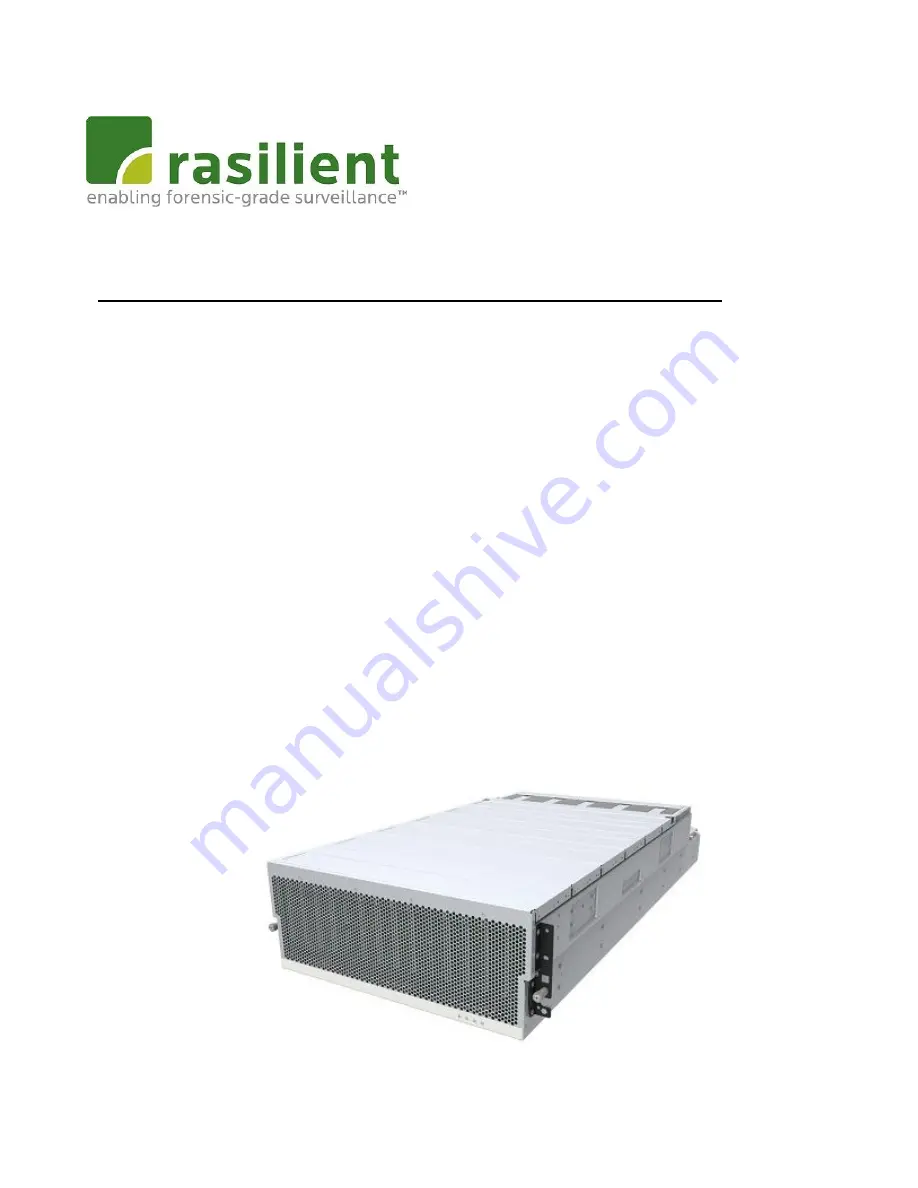
Page 15: ...sure of data contained on this page is subject to the restriction on the title page of this document 15 Product Appearance Figure below is a trimetric view of the chassis Figure 1 PS390e System Trimet...

Page 16: ...tained on this page is subject to the restriction on the title page of this document 16 Figure below is a rear view of the chassis showing PSU DC DC and ESM canisters Figures below show the indicator...

Page 17: ...iption Drive Fault Summary LED Amber On Any Drive have fault in the enclosure Off All Drives works fine Enclosure Power LED Green On Enclosure Power LED Off Enclosure power is off Enclosure Fault LED...

Page 18: ...ntained on this page is subject to the restriction on the title page of this document 18 Figure 5 Indicators on Top of PS390e Indicator information Description Fan 1 Fan 5 Fan fault indicators Table 1...

Page 19: ...disclosure of data contained on this page is subject to the restriction on the title page of this document 19 Indicator Description PSU1 PSU 1 PSU2 PSU 2 DC1 DC DC Module 1 ESM1 ESM Canister A Figure...

Page 20: ...or disclosure of data contained on this page is subject to the restriction on the title page of this document 20 DC2 DC DC Module 2 PSU3 PSU 3 PSU4 PSU 4 ESM2 ESM Canister B Table 1 3 Indicator inform...

Page 21: ...this document 21 Figure below top view of the chassis showing PS390E numbering as well Figure 7 Drive Slot Map Drive slots 0 11 are best to use for SSD performance When install the drive start from th...

Page 22: ...frequency of your power source match the voltage and frequency inscribed on the equipment s electrical rating label Never push objects of any kind through openings in the equipment Dangerous voltages...

Page 23: ...refer to the power rating label or the user documentation supplied with that option CAUTION this product is designed to work with power systems having a grounded neutral grounded return for DC powere...

Page 24: ...ling procedures wherever this symbol occurs during the system integration 2 All Employees must attend an ESD training class prior to performing any system or board handling If you have not been proper...

Page 25: ...he operating ambient temperature of the rack environment may be greater than room ambient Therefore consideration should be given to installing the equipment in an environment compatible with the maxi...

Page 26: ...pment must not be used as a shelf or workspace Do not add weight to rack mounted equipment The following warnings apply to Racks and Rack Mounted systems CAUTION For safety equipment should always be...

Page 27: ...omply with the limits for a Class A digital device pursuant to Part 15 of the FCC Rules These limits are designed to provide reasonable protection against harmful interference when the equipment is op...

Page 28: ...uipment WEEE In accordance with European Directive 2012 19 EU on Waste Electrical and Electronic Equipment WEEE the presence of the above symbol on the product or on its packaging indicates that this...

Page 29: ...contained on this page is subject to the restriction on the title page of this document 29 If this equipment is used in a domestic environment radio interference may occur in which case the user may...

Page 30: ...he title page of this document 30 Necessary Tools We recommend the users to prepare and use the following tools for equipment installation 1 ESD Protection the users can wrap them around the wrist 2 P...

Page 31: ...l out Chassis from Rack Drive Assembly Push Chassis into Rack Check the Installation Environment Check the cabinet or mounting bracket ensure that rack or mounting bracket should be able to hold eight...

Page 32: ...he package and check whether any item is in poor condition If you find damage contact the local authorized Rasilient agent After unpacking please be sure to examine and check the parts in good conditi...

Page 33: ...sure of data contained on this page is subject to the restriction on the title page of this document 33 Step 2 Install the inner member onto the chassis Figure 15 Remove the Inner Rail Figure 16 Insta...

Page 34: ...or disclosure of data contained on this page is subject to the restriction on the title page of this document 34 The inner rail fixed on chassis by 8 pcs screw on each side 4 pcs screw M4xL6 Figure 17...

Page 35: ...of data contained on this page is subject to the restriction on the title page of this document 35 Step 3 Install the CMA bracket Step 4 Install the outer rail onto the rack post Figure 18 Install CMA...

Page 36: ...he chassis to complete the installation 1 Pull the middle rail fully extended in locked position 2 Ensure ball bearing retainer is located at the front of the middle rail 3 Aim the rear end of inner r...

Page 37: ...on this page is subject to the restriction on the title page of this document 37 6 Tighten chassis with rack by thumb screw on chassis ear during normal operating and the shipping screw is tightened...

Page 38: ...Rasilient Confidential Use or disclosure of data contained on this page is subject to the restriction on the title page of this document 38 Figure 22 Front Bezel Screw...

Page 39: ...his page is subject to the restriction on the title page of this document 39 Rail Kit Removal Step 1 Remove the chassis from the rack 1 Loosen shipping screw to pull out chassis 2 Pull the disconnect...

Page 40: ...tep 2 Remove the bracket Drive This section simply introduces the Drive assemble process which will happen on customer side For security reasons it is recommended that the equipment should be installe...

Page 41: ...ocument 41 WARNING Hard drive configuration for safe installation and use 1 When the equipment is installed with rack install hard drive in sequential from slot 1 to 90 2 When the equipment is putted...

Page 42: ...nch your fingers WARNING When install the system in the rack be sure to start from the bottom to the top Do not install the system in the rack from top to bottom Drive Installation Install 3 5 inch Dr...

Page 43: ...restriction on the title page of this document 43 3 5 inch Drive 3 5 inch Hard Disk X1 Screw X 4 6 32 L5 NYLOK Carrier X 1 Screwdriver used PH2 Screw torque 6 0 5 kgf cm 5 lbf inch Step 1 Put hard dis...

Page 44: ...Rasilient Confidential Use or disclosure of data contained on this page is subject to the restriction on the title page of this document 44 Figure 29 3 5 Drive Assembly Sequence...

Page 45: ...kit with all the parts necessary for the installation Step As Figures below show a detail sequence of pictures that show the proper kits and method of assembling These methods must be followed or fail...

Page 46: ...ient Confidential Use or disclosure of data contained on this page is subject to the restriction on the title page of this document 46 Step 2 Fixed hard disk by screws Figure 31 2 5 Drive Assembly Seq...

Page 47: ...age is subject to the restriction on the title page of this document 47 NOTE Please make sure the Drives have been installed correctly and tightly otherwise will affect the use Install Drives into cha...

Page 48: ...the title page of this document 48 Step 2 Pull out install the Drive carrier Pictures below will show the details for proper drive installation and removal process Assemble HDD into Chassis 1 Alignin...

Page 49: ...Use or disclosure of data contained on this page is subject to the restriction on the title page of this document 49 2 Rotate the handle down to lock the HDD into the chassis 3 The bottom toe will en...

Page 50: ...onfidential Use or disclosure of data contained on this page is subject to the restriction on the title page of this document 50 4 The second stage will engage to fully close Figure 34 Assemble HDD in...

Page 51: ...tion on the title page of this document 51 Remove HDD from Chassis Step 1 To release the carrier simply push slide into the touch point Step 2 The handle will open automatically Pull the drive out of...

Page 52: ...Confidential Use or disclosure of data contained on this page is subject to the restriction on the title page of this document 52 Push Chassis into Rack Figure 36 Close Chassis Figure 37 Push Chassis...

Page 53: ...ximum time is 10 minutes 2 PSU replacement maximum time is 10 minutes 3 System fan module replacement maximum time is 10 minutes 4 DC DC module replacement maximum time is 10 minutes 5 Drive replaceme...

Page 54: ...Mini SAS HD link status LED Green o Steady On Linked o Blink data transfer o Off No Link No 5 No 7 No 8 No 10 ESM Mini SAS HD link fault LED Amber o On Link fault o Off Normal Mini SAS HD port There a...

Page 55: ...entory information of FRUs and enclosure log Display Clear system event and operation log port SAS Expander port status display power Display Change power status of FRU Drives threshold Display or set...

Page 56: ...this page is subject to the restriction on the title page of this document 56 ESM Canister ESM Canister Installation Press the latch and rotate the ESM Canister handle with a stop angle and push it i...

Page 57: ...ata contained on this page is subject to the restriction on the title page of this document 57 ESM Canister Removal Press the latch and rotate the ESM Canister handle then pull the canister out of the...

Page 58: ...rview The PS390E storage enclosure is powered by four 1200 watt redundant Power Supply Units with following features 1200w 2 2 Redundant 80Plus Platinum Level Input 200 240VAC via IEC 320 C 14 inlet o...

Page 59: ...supply continues to operate high temp high power high current slow FAN 1Hz Blink Amber Power supply critical event causing a shutdown failure OCP OVP FAN fail Amber AC Power Cord The AC power cord is...

Page 60: ...ge is subject to the restriction on the title page of this document 60 PSU The appearance of PSU is shown as below PSU Installation Rotate the PSU handle with a suitable angle and push the PSU into th...

Page 61: ...disclosure of data contained on this page is subject to the restriction on the title page of this document 61 PSU Removal Rotate the handle and then pull the PSU out of the chassis Figure 44 PSU Insta...

Page 62: ...f this document 62 Fan Modules Overview The PS390E enclosure houses five fan modules in the rear for drive Fan Module LED Refer to the picture below for the Fan Module top view Each Fan Module has one...

Page 63: ...introduces the fan modules installation process Fan Module Installation Make the fan module and fan slot alignment then insert fan module in the system Rotate the handle down until heard Click the in...

Page 64: ...Rasilient Confidential Use or disclosure of data contained on this page is subject to the restriction on the title page of this document 64 Figure 49 Fan Module Removal...

Page 65: ...ata contained on this page is subject to the restriction on the title page of this document 65 NOTE Users should not disassemble the fan module without Rasilient engineer authority DC to DC Figure 50...

Page 66: ...Rasilient Confidential Use or disclosure of data contained on this page is subject to the restriction on the title page of this document 66 Assemble into chassis Figure 52 Assemble DC DC into Chassis...

Page 67: ...striction on the title page of this document 67 Remove DC DC from Chassis Drive Carrier Drive Carrier 3 4 1 1 Overview The drive carrier side view refers to below It is designed to support both 2 5 in...

Page 68: ...ive Carrier front view There are two indicators on the front face One shows drive link active status The other one is the drive fault LED Drive Active Ready LED Green Controlled by drives directly Dri...

Page 69: ...the check please wire the equipment and access to electricity Follow the steps below 1 Connecting the power cable s and electricity see Connecting and securing the power cable s 2 Connecting another...

Page 70: ...of this document 70 NOTE Turn on your enclosure check all the LEDs are lighting normally If not check the cables or reference Troubleshooting enclosure startup failure Securing the power cable s Afte...

Page 71: ...ential Use or disclosure of data contained on this page is subject to the restriction on the title page of this document 71 Open Status of Routing the cables Figure 58 Bottom Layer CMA Figure 57 Secur...

Page 72: ...lient Confidential Use or disclosure of data contained on this page is subject to the restriction on the title page of this document 72 Figure 59 Top Layer CMA Figure 60 Open Status of Routing the cab...

Page 73: ...Close Status of Routing the cables Connect the enclosure To connect the enclosure to a host system 1 Connect the SAS cable to ESM Mini SAS HD connector on the storage enclosure and to the PS7012 or PS...

Page 74: ...cable to the ESM or the RAID Application controller 2 To remove the SAS cable pull the pull tab to release the cable from the connector on the ESM and the RAID Application Controllers Figure 62 Conne...

Page 75: ...It only supports single controller configuration for SATA drives Single port configuration Single Port configuration the enclosures are daisy chained with one of the ESMs connected to a single port on...

Page 76: ...ential Use or disclosure of data contained on this page is subject to the restriction on the title page of this document 76 Figure 64 Redundant Configuration Figure 65 PS7012 to PS390e SAS connections...

Reviews: