background image

Manual-1

SRM 66

SPLITTER ROUTER MIXER

OPERATORS MANUAL

Quick Start

Before complaining about having to install the 

SRM 66

 in 

the rack 

twice

 (because you forgot to set the internal highpass 

filters ahead of time), take note that the very first (non-joke) 

line in this manual is: 

Before installing the 

SRM 66

 in a rack, 

be sure the internally switchable 80 Hertz highpass filters are set 

as desired. They are shipped with the filters in the OUT (disabled) 

position. (See the bottom of page Manual-2 to enable these filters.)


If you were smart enough to read this much of the manual, this 

paragraph may already have saved you a few minutes of your 

life – you’re welcome. If you’ve learned the hard way, hopefully 

you’ve learned an important lesson – read at least the first line in 

the manual first.

Make all connections with the power and amplifiers 

off

. The 

SRM 66

 is fully balanced and equipped with removable 5-posi-

tion Euroblock connectors. Inputs and Outputs are arranged on 

Euroblocks in pairs, i.e., 1&2, 3&4, 5&6.

Be sure the 

FP LOCK

 switch (on rear) is in the 

out

 position 

to enable programming from the front panel.

Apply power so the 

PWR

 LED lights and LCD screen glows 

with the 

SRM 66

 welcome marquee. During initialization, the 

startup muting circuit immediately starts counting down from 

40 in the Limiter Gain Reduction area of the display. Adjust the 

VIEWING ANGLE

 with a miniature screwdriver if necessary.

With signal applied to the Inputs, watch the 

MIX INPUT 

HEADROOM

 indicators. These verify correct setting of the 

Output of the previous device and the rear panel Input 

GAIN


switches. Adjust so that 

4 dB

 lights during peaks.

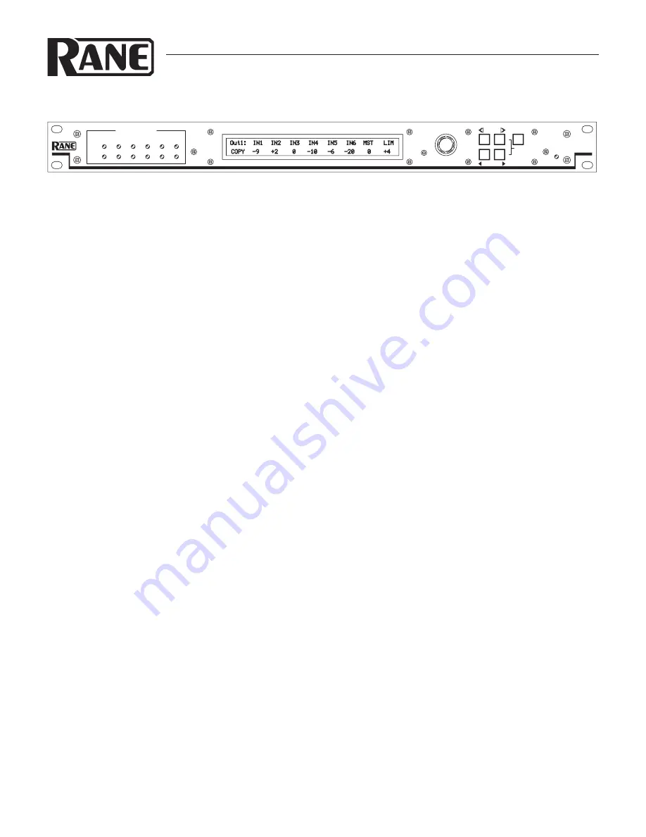
Navigating the LCD Edit pages is simple. The top buttons 

marked 

<<

 and 

>>

 are the left/right Page scroll buttons. These 

navigate to Output pages 1 through 6, the assign 

Outputs to 

Output Group

 page, the assign 

Remote to Group

 page, the assign 

Group to Master Remote

 page, the

 Group Levels

 page, and the 

Memory

 page.

WEAR PARTS:

 This product contains no wear parts.

The bottom buttons marked 

<

 and 

>

 are the left/right cursor 

buttons. These select the (underlined) parameter to edit.

Rotating the 

DATA

 knob changes the parameter setting.

Let’s start by navigating to Output 1’s page. Move the cursor 

under 

IN1

. With a signal driving Input 1 and a working ampli-

fier connected to Output 1, adjust the 

DATA

 knob to the desired 

level. Adjust any other Input going to Output 1. 

MST

 controls 

the Master level of Output 1. 

LIM

  sets the Limit Threshold of 

the Limiter circuit for Output 1.

To Copy settings from Output 1 to any other Output, move 

the cursor to 

Copy

. Press the 

EXE

 button. The display now 

reads 

Paste

. Change the page to the one you want these same 

settings in, and press 

EXE

 again. The settings have now been 

pasted into the new Output.

Settings may be Stored and Recalled in the Memory Page. To 

Store, select the 

Store

 field, select a Memory number with the 

DATA

 wheel and press 

EXE

. To Recall, select the 

Recall

 field, 

select a Memory number with the 

DATA

 wheel and press 

EXE

Look deeper into this manual for information on remote control 

of Memories, level adjustments and, the most powerful feature 

of the SRM 66, Output Groups which “link” Output levels. A 

Master Remote feature allows controlling the level of any Output 

Groups assigned to it.

For best signal control and dynamic range, 

turn the Master 

Output off when no Inputs are routed to a given output

.

CAUTION: Never connect anything except an approved 

Rane power supply to the thing that looks like a red telephone 
jack on the rear of the SRM 66. 

This is an 18 VAC center 

tapped power input. Consult the Rane factory for a replacement 

or substitute.

16dB

4dB

SPLITTER

MIXER

ROUTER

SRM 66

1

4

3

2

MIX INPUT HEADROOM

6

5

EXE

DATA

PWR

SHIFT

VIEWING

N

ANGLE

X

M

I

A

M

Summary of Contents for SRM 66

Page 1: ...through 6 the assign Outputs to Output Group page the assign Remote to Group page the assign Group to Master Remote page the Group Levels page and the Memory page WEAR PARTS This product contains no wear parts The bottom buttons marked and are the left right cursor buttons These select the underlined parameter to edit Rotating the DATA knob changes the parameter setting Let s start by navigating t...

Page 2: ... left or right When any parameter is selected the DATA wheel adjusts that parameter When the EXE button is held and MIN is pressed the selected parameter jumps to its lowest value see EXE Execute button Several commands are implemented with this button Holding down EXE while pressing MAX alters the selected parameter to its highest nominal value Holding down EXE while pressing MIN alters the selec...

Page 3: ...Configuration feature found in SRM Exchange software See DSC 1 SRM Exchange software on page Manual 9 REMOTE INTERFACE PORT RIP This Port supports up to seven optional SR 1L Smart digital Remote controls see page Manual 6 Each Remote may be assigned to adjust the Level of any one of the six SRM 66 Output Groups or the Master Group OUTPUT GAIN switches These assist setting the optimal gain structure...

Page 4: ...in the grounding inside a unit s or between units somewhere Your mission is to discover how your particular system wants to be grounded Try these things 1 Try combinations of lifting grounds on units that are supplied with ground lift switches or links Other than in your own home it is illegal and unsafe to use 2 prong to 3 prong AC line cord cheaters even though this is a common short term remedy...

Page 5: ...emory page an asterisk appears in this field whenever the current working Memory does not match the last recalled Memory Programming the SRM 66 Programming each SRM 66 Output requires only one edit page as in Figure 1 Note that unique Input mix levels are pos sible for each Output All adjustments are in 1 dB steps The following parameters define each Output IN1 Input one mix Level 6 dB to 25 dB Off I...

Page 6: ... 1 SRM Exchange Software When using the SRM 66 s Master Slave feature RIP must be set to SLAVE A single SR 1L can control Output Groups across multiple SRM 66 s For information on Master Slave functional ity see the RaneNote Advanced Applications of the Ingenious SRM 66 and SR 1L SR 1L Remotes The SRM 66 provides a Remote Interface Port which sup ports up to seven optional SR 1L Smart Remote contr...

Page 7: ...e solution to recalling four Memories from a remote location The MRS 4 mounts in a standard U S electrical box with a minimum depth of 2 25 5 5 cm If connected to the MRP in Normal mode this remote allows up to 4 Memories to be recalled See the Nor mal section of Table 1 on the following page See the MRS 4 Data Sheet for hookup and operating instructions RCP 3 and RCP 4 Room Combining Panels The o...

Page 8: ...short list of suitable cable types CONSOLIDATED ELECTRONIC WIRE AND CABLE Plenum cable Unshielded remote control signal cable CAT 9896 Shielded remote control signal cable CAT 9877 or 9852 WEICO WIRE CABLE INC Communication and control cable Multiconductor unshielded CAT 7606 ALPHA Communication and control cable Multiconductor unshielded CAT 1175C BELDEN Unshielded remote control signal cable CAT...

Page 9: ...link ing multiple Remotes together in one condi tion while separating them in another In Memory 2 the Mas ter can control both Output Groups while permitting individual control within each divided room Figure 10 Room Combining System One thing to keep in mind in such a situation is the Group s Level is not stored in each Memory This allows you to change Memories without it resetting the Group s Le...

Page 10: ...ion ally required in applications with multiple contact closure sen sors This feature is provided via the completely programmable SRM 66 Memory Recall Port using SRM Exchange software see the DSC 1 Data Sheet To externally control an SRM 66 from an AMX or Crestron first read Using a Control System with an SRM 66 There are 3 modes of operation for the SRM 66 RIP DSC SLAVE To externally control the S...

Reviews: