RAIMONDI SA 25, Use And Maintenance Manual
The RAIMONDI SA 25 is a high-quality product designed for heavy-duty lifting applications. Ensure proper operation and safety by referencing the Use And Maintenance Manual available for free download from manualshive.com. This comprehensive manual provides detailed instructions to keep your equipment in top condition.
Share
Download


Reviews:
No comments
Related manuals for SA 25

PTS-250
Brand: Parker Pages: 14

356347 2004
Brand: Parkside Pages: 125

PHKSA 20-Li A2
Brand: Parkside Pages: 117

BS2031
Brand: Valex Pages: 24

14-10
Brand: Dake Pages: 17

PRO-SB1800
Brand: Promaker Pages: 96

SXC208
Brand: Sunex Tools Pages: 10

CG-PSB
Brand: Hitachi Pages: 48

CG-EX
Brand: Hitachi Pages: 16
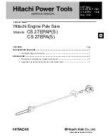
CS 27EPA(S)
Brand: Hitachi Pages: 35

FBS-700
Brand: Ferm Pages: 32

SSM1007
Brand: Ferm Pages: 92

MI-92100
Brand: Magnum Industrial Pages: 21

Quality MACHINERY TS10SEW.V2
Brand: Sealey Pages: 6

CP20VCS
Brand: Sealey Pages: 5

43 285
Brand: F.F. Group Pages: 70

216
Brand: Whirlwind Pages: 25

NC1300CS
Brand: Dexter Power Pages: 28


