background image

  Radio Systems, Inc. 

  CT-2002 Clock/Timer Manual

For Models: 

CT-2002 Desktop
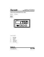
CT-2002 Thin
CT-2002 Large 2”
CT-2002 Large 4”
CT-2002 Console
CT-2002 Desktop GPS
CT-2002 2” GPS
CT-SYNC Clock to PC Synchronization Kit
GPS-SYNC GPS to PC Synchronization Kit

*Updated SEPTEMBER

 2008

Applies to units

 with  

software versions

 CT-2007 


Includes Remote

 Control Enhancements


& New Daylight

 Savings Time Schedule

Summary of Contents for CT-2002 2" GPS

Page 1: ...Large 2 CT 2002 Large 4 CT 2002 Console CT 2002 Desktop GPS CT 2002 2 GPS CT SYNC Clock to PC Synchronization Kit GPS SYNC GPS to PC Synchronization Kit Updated SEPTEMBER 2008 Applies to units with software versions CT 2007 Includes Remote Control Enhancements New Daylight Savings Time Schedule ...

Page 2: ...ilize as Slave Timer Display 7 Time of Day Offset 8 Infrared Remote Control Up Timing 9 Down Timing 9 Storing Down Times 9 Recalling Stored Down Times 10 On Power Up 10 Time of Day Set 10 Setting to Slave Display 10 Setup Functions 11 Infrared Remote Control Diagram 13 GPS Driver Additional Operating Instructions 14 Setup Programming 14 Top of Hour Closure 14 Connections and Installation 14 Operat...

Page 3: ...ns between CT 2002 Stand Alone Models 20 Using RJ 45 Patch Cords Serial Clock Timer Connections between CT 2002 Stand Alone Models 21 Using Twisted Pair Wiring GPS Antenna Wiring Diagrams 22 CT 2002 GPS Dip Switch Settings Diagram 23 Policies Warranty 24 Repair Policy 24 Return Instructions 24 Note Master Desktop and Master 2 models are no longer manufactured Analog clocks are no longer manufactur...

Page 4: ...mote control CT 2002 Thin 1 deep x 3 high stick on clock timer with 3 4 LED displays featuring the same functions as the desktop unit but in a smaller profile cabinet CT 2002 2 2 deep x 5 high clock timer display with 2 high LED display and the same features set as the desktop and thin units CT 2002 4 2 deep x 5 high clock timer display with 4 high LED display and the same features set as the desk...

Page 5: ... of Day is supplied to the CT 2002 slave mode it will not be possible to enter the Time of Day set mode Setting the time of day can either be done at the master unit or the displayed hours can be offset via the IR Remote Control 1 Press the mode button to select the Time of Day display The Clock LED will illuminate 2 Desktop and Thin models press and hold the STOP and START buttons The Set LED wil...

Page 6: ...ime of day will immediately synchronize to the master unit readout 4 Time of Day setting is now no longer available on this slave display Time of Day setting must be made to the unit providing the serial Time of Day data 5 If the data link is lost the clock will revert to stand alone local operation and the sync LED will extinguish 6 Local timer functions continue to be available as described on t...

Page 7: ...nd press the MEM 6 button on the IR remote control Confirm that the SYNC LED on the slave lights and that the slave display shows the timer data from the up stream display unit 6 To return the slave display to none slaving timer stand alone functionality press the RESET button on the IR remote control with the slave display in the timer mode The SYNC LED will extinguish and the timer display will ...

Page 8: ... desired to be displayed when the top of hour closure is received Note that hours displayed will not be affected Note that top of hour is only active prior to and after the hour to avoid false triggers at other times See manual page 12 for programming instructions To offset serial time input from and upstream GPS or Master clock in the serial chain RS serial time code or SMTPE time code allowed Us...

Page 9: ...ions see page 10 4 Press the Stop Button to stop down timing 5 Press the Start Button to resume down timing 6 Press the Reset Button once to recall the entered down time Repeat steps 3 through 6 as desired 7 Press the Reset Button two times to exit the down mode and to clear the display and return to up timing mode Storing Down Times The IR Remote Control can be used to store up to six down times ...

Page 10: ...al time of day is being supplied by a master clock or GPS system However the displayed time may be offset up to 23 hours see IR Remote Setup Functions page 13 1 Press the Clock Mode Button to put the CT 2002 into the Clock Mode The Clock LED will illuminate 2 Press the Time of Day set button The Set LED will illuminate 3 Using the numeric keypad on the IR Remote Control enter the correct time The ...

Page 11: ...Press the Clock set button to toggle between Radio Systems 1 rS1 format Radio Systems 2 rS2 format and SMPTE SP format SMPTE enable the serial input to read standard SMPTE format no drop frame rS1 enables the serial inputs to read Radio Systems serial time of day format as generated by Radio Systems GPS Master and stand alone clocks rS2 enables the serial inputs to read Radio Systems serial time o...

Page 12: ...tion 6 above Option 10 Top of Hour Reset Offset A wired remote input is available for top of hour reset The default operation is to reset the time of day to 00 min s 00 sec s Use the numeric keypad to reset to a different time minutes and seconds When the displayed time of day is within a 5 minute window of the stored top of hour time and the wired remote input is activated the displayed time will...

Page 13: ...begin down timing 5 Press the Stop Button to stop down timing 6 Press the Start Button to resume down timing 7 Press the Reset Button once to recall the selected down time Repeat steps 3 through 6 as desired 8 Press the Reset Button two times to exit the down mode return to up timing mode and clear the display Note Stored Down Time 1 can be recalled remotely via parallel remote control wiring See ...

Page 14: ...r this feature is off Top of Hour Closure GPS Master driver units on 2 4 and desktop provide a top of hour closure available as a C form relay closure for 250 ms occurring at the top of each hour The C form contacts are available on the rear remote control barrier strip connector on pins 15 and 16 last two terminals on the strip See Remote Connection diagram p19 of this manual for connections Conn...

Page 15: ...time will be updated and the data lamps re illuminated 3 Front panel master GPS controls cannot be used to set or change the digitally displayed time of day but the time mode may be used to adjust the time on any analog clocks connected and the START STOP and RESET switches may be used in the timer mode See the Analog Clock Connection and Use sec tion for operating details GPS Error Codes These tw...

Page 16: ...ion Kit This hardware and software kit allows a PC s time base to be updated via RS serial time code OR allows a PC s time base to output RS serial time code Connection to the PC is via USB and connection to CT 2002 is via two wire twisted pair serial cable The kit includes a USB to RS422 converter and software One included software program installs in any Windows 2000 or higher OS and automatical...

Page 17: ...ut 150ft is the maximum distance that the antenna cable may be extended without the use of the active RS 485 converter boxes below CT 250 GPS 250ft Active Extension Kit 250ft of shielded CAT 5 cable with active RS 232 to RS 485 extender biscuits GPS antenna plugs into far side and near is connected to GPS clock via an RJ 45 patch cable provided Converter biscuits are active and powered via the GPS...

Page 18: ... ote te s s o o Desktop o e s ote t t stee o es ot s pp e st e st e GND 15V DC IN 1 2 3 4 5 6 7 8 9 10 1112131415 1617181920 Anci ary 16 Ground 17 Down Time Closure at 0 18 Top of Hour Input 19 Ground 20 15V DC emote ont ro 6 Ground 7 Start 8 Stop 9 Reset 10 Mode oc Triggers 11 Ground 12 Time Closure 1 13 Time Closure 2 14 Time Closure 3 15 Time Closure 4 Seria Synchroni ing ata 1 Serial In 2 Seri...

Page 19: ...made cables observe pinouts to right SERIAL INPUT TERMINATION RJ 45 OUT RJ 45 IN GND 15V DC IN RJ 45 SHIELD TO GND 1 2 3 4 5 6 7 8 9 10 1112131415 1617181920 Ancillary I O 16 Ground 17 Down Time Closure a t 0 18 Top of Hour Input 19 Ground 20 15V DC Remote Control 6 Ground 7 Start 8 Stop 9 Reset 10 Mode Clock Triggers 11 Ground 12 Time Closure 1 13 Time Closure 2 14 Time Closure 3 15 Time Closure ...

Page 20: ...e Closure 3 15 Time Closure 4 Serial Synchronizing Data 1 Serial In 2 Serial In 3 Ground 4 Serial Out 5 Serial Out REMOTE CONTROL BARRIER STRIP PIN OUTS CT 2002 Large FOR MASTER TIME SYNC VIA RADIO SYSTEMS or SMPTE SERIAL DATA wire timer displays serial in with Radio Systems or SMPTE Time of Day serial input for accurate time readout Accurate time will be read by all serially connected displays Ti...

Page 21: ... S E R IA L O U T S E R IA L O U T G N D S T A R T S W IT C H S T O P S W IT C H R E S E T S W IT C H M O D E S W IT C H G N D T IM E C L O S U R E 1 T IM E C L O S U R E 2 T IM E C L O S U R E 3 T IM E C L O S U R E 4 G N D D O W N TI M E C LO S U R E AT 0 T O H R E S E T IN P U T R J 4 5 O U T R J 4 5 IN 9V DC IN MODEL CT 2002 DESKTOP Part No 14409 S E R IA L IN S E R IA L IN R J 4 5 S H IE L D ...

Page 22: ...USA 1 856 467 8000 www radiosystems com Satellite Receiver Antenna Note The cable used must be shielded with the ground connected to pin 1 on both ends For cable lengths over 150 install Radio Systems RS 485 balancing amplifiers Pin 1 Ground Shield Pin 2 15V Pin 4 1 P P S Pin 6 Data 87654321 RJ 45 Patch Cable 250 factory shielded cable or user provided shielded 4 conductor cable up to 500 Note Shi...

Page 23: ...Connection Diagrams CT 2002 GPS Dip Switch Settings India New Delhi Time 5 1 2 hours ahead of GMT No Daylight Savings 12 hour Analog Clocks connected Note Special software prom p n 16119 required Prom adds 1 2 hour to all time offset settings ...

Page 24: ...ring the warranty period there will be no charge for parts or service made to units which show no sign of misuse by customer or lightning caused damage The customer is responsible for the cost of shipping their unit back to Radio Systems for repair During the warranty period shipment of small parts and assemblies may also be made at a charge to the user Emergency shipments of replacement parts and...

Page 25: ... 856 467 8000 Fax 856 467 3044 601 Heron Drive Logan Township New Jersey 08085 www radiosystems com For Assy Part 14691 rev 9 09 ...

Reviews: