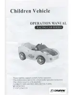
background image

Radio control model

MAGIC

Wingspan:         1148mm (45.2”)
Radio       :         4 channels
Engine     :          .25 -.32 two-stroke
                          

INSTRUCTION MANUAL

WARNING!

This radio control model is not a toy. If modified or flow carelessly it could go out of control 
and cause serious bodily injury or property damage.
Before flying your airplane, ensure the air field is spacious enough.
Always fly it outdoors in safe areas with no debris or obstacles.

VQA038

VQA039

PYLON RACING

Summary of Contents for VQA038

Page 1: ...NING This radio control model is not a toy If modified or flow carelessly it could go out of control and cause serious bodily injury or property damage Before flying your airplane ensure the air field is spacious enough Always fly it outdoors in safe areas with no debris or obstacles VQA038 VQA039 PYLON RACING ...

Page 2: ...ned right Use an iron or heat gun Start as low setting Increase the setting if necessary If it is too high you may damage the covering Low setting SILICON EPOXY A EPOXY B CA GLUE Epoxy Glue 30 minutes type 5 minutes type Silicon Glue Cyanoacrylate Glue Minimum 4 channel radio for airplane 9 x 6 for 25 2 cycle engine 9 5x6 for 32 2 cycle engine Silicone tube Extension for aileron servo 25 32 2 cycl...

Page 3: ...ene and a paper towel 6 Apply masking tape at the wing joint to hold the wing together securely while the epoxy cures Or using litter CA glue 1 Install the rubber servo grommets and eyelets in the aileron servo and place the servo into the aileron servo tray as shown Using a pencil mark the poisi tion of the four servo mounting holes 2 Remove the servo from the servo tray Drill the four mounting h...

Page 4: ...of the wing as show 3 Slide one wheel onto each of the landing gear axles and secure them with the supplied wheel collars Hinge Line Control horn Alignment A B 2x12mm screw 6 Horizontal stabilizer 2mm A A A A B B B B 1 Trial pit the horizontal stabilizer in place on the fuselage 2 Use a pencil to trace around the bottom of the stabilizer where it meets the fuselage 3 Remove the horizontal stabiliz...

Page 5: ... will make the canopy white residue 8 Tail wheel 9 Canopy Control horn 1 2x12mm screw 2 1 3x10mm screw 2 2mm collar CA Make sure to glue securely If not properly glued a failure in flight may occur 1 2 Clear canopy Cockpit floor A B or 5 min 30 min WARNING When removing any covering from the airframe please ensure that you secure the cut edge with CA or similar cement This will ensure the covering...

Page 6: ...e four marks made in step 1 3 Insert the four blind nuts in to the bottom of engine mounts 4 Reposition the engine on to the engine mounts and secure it in place with four 3x20mm screw Tune pipe option FUEL TANK 3xmm blind nut Engine mount SIDE VIEW 2 3mm Checking for leaks block the vents and blow into the feed if in doubt submersing the tank in a blow of water will show up any problems Blow Wate...

Page 7: ...3 Linkages 8 10mm 10 12mm 25mm AILERON STROKE ELEVATOR STROKE RUDDER STROKE 14 Control surface Linkage stopper 3 1 Connector Elevator pushrod x2 X 5 16 13 32 5 16 13 32 8 10mm 10 12mm 13 32 15 32 13 32 15 32 25mm 1 1 Throttle push rod X 3mm set Screw 2 mm Elevator pushrod X 3mm set Screw 2 mm THROTTLE RUDDER SERVO Throttle pushrod D 3 64 1 2mm Rudder pushrod D 5 64 2mm ELEVATOR SERVO Adjust the tr...

Page 8: ...e elevator rudder ailerons and throttle ELEVATOR AILERON RUDDER Always take off and landing your airplane into the wind Adjust the engine always from behind but never from infront or the sides as rotating propeller may badly injure you Do not allow watching people to get too close to a rotating propeller Ensure the spinner and propeller are securely attached Immediately disure defective propeller ...

Reviews: