1of2
6 CORPORATE PARKWAY
GOOSE CREEK SC 29445
www quoizel com
,
.
.
.
Thank you for purchasing a Quoizel product.
Need assistance with parts or assembly? Call Quoizel customer service at 1-631-273-2700
or visit us on-line at www.quoizel.com
2015 QuoizelInc.
Please go to
for product cleaning tips. Go to the
selection.
(1) Medium Base bulb 100W Maximum, Alternate bulb (1) 23W CFL.
www.quoizel.com
Care + Maintenance
Light Source:
Tools Required:
Flathead screwdriver, Phillips screwdriver, pliers, wire cutters, wire strippers, electrical tape, safety glasses.
Estimated Assembly Time:
Preparation:
20-30 minutes
Identify and inspect all parts before beginning installation. Check package content list and diagrams below to be sure all parts are
present. If any parts are missing or damaged, do not attempt to assemble, install, or operate the fixture. Contact customer service for replacement
parts.
Warnings and Cautions
Turn off electricity at circuit breaker or main fuse box before installation. Consult a licensed electrician if in doubt.
These instructions are provided for your safety. It is very important you read them completely before installing the fixture. We strongly
recommend that a licensed, professional electrician perform the installation.
Disconnect fixture from power source before replacing bulbs. Make sure bulbs are given sufficient time to cool before removal. Do not subject
glass parts to any shock while in operation or shattering may result.
Package Contents
Fixture Body
x 1
B
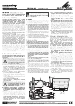
STEP 1
Install Bulb
-
A. Remove the Fixture Hood from the
Cage by unscrewing Screws on the
Fixture Hood.
B. This fixture uses standard bulb with a
medium screw base. Maximum 100
watts. Insert bulb and screw snugly into
place.
C. Attach the Fixture Hood back onto the
top edge of the Cage and secure with
the previously removed Screws. Hand
tighten until snug.
Screw
Cage
Fixture
Hood
Figure 1
STEP 2
Drill Pilot Holes on Post
-
A. Carefully fit the Post Fitter over the
end of the Post (not supplied),
making sure the Post Fitter is fully
seated.
B. Mark the drill point for the (3)
Mounting Screws, using (3)
Mounting Holes as reference. After
marking hole locations, remove
fixture from post and drill 1/16” pilot
holes for screws.
Post
Post Fitter
Figure 2
Mounting Hole
STEP 3 - Wire Connections
A. Use standard wire connectors (not included) to make all wire
connections. (Connectors are not included with fixture.) Twist
White wire
from supply
White wire
from fixture
Black wire from
supply (or Red)
Black wire
from fixture
Ground wire
from supply
Ground wire
from fixture
Figure 3
A
Mounting
Screw
x 3
June2015
Assembly Instruction Sheet #IS-SNN9009
For Styles SNN9009K, SNN9009PN and SNN9009W
Bulb
Socket
STEP 4
-
Attach Fixture Body to Post
A. Coat the top 1” of the Post with Clear
Silicone Caulk (not supplied) and
position the Post Fitter onto the Post. Be
sure to seat it completely, aligning the
holes in the Fitter with the 1/16” Pilot
Holes drilled into the Post.
B. Secure the Fixture to Post with (3)
Mounting Screws (A).
Your fixture is now assembled and
ready to use. Enjoy!
Post
Post Fitter
Figure 4
Mounting Hole
(Step 3 Continued)
connectors until wires are tightly joined together. Wrap each
connection with approved electrical tape and carefully stuff all the
connected wires into the Outlet Box.
HOW TO REPLACE GLASS PANELS
Screw
Lock
Screw
Fixture Hood
Glass
Holder
Glass
Panel
Cage
A.
Fixture
Hood and remove Fixture Hood
from the Cage.
B. Remove Bulb from inside of the
Cage.
C. Remove Lock Screws from the
Cage and remove Glass Holders.
Replace Glass Panels from the
Cage and then re-install Glass
Holders to secure them. Secure
with removed Lock Screws.
D. Re-install the Bulb and re-attach
the Fixture Hood to the Cage.
Secure with Screws and hand
tighten until snug.
Unlock Screws on the
Figure 5
Bulb