Qume QumeTrak 242, Руководство по обслуживанию
Технический руководство по обслуживанию для Qume QumeTrak 242 доступен для бесплатного скачивания на нашем сайте. Этот ручной труд позволяет пользователям осуществлять обслуживание своего устройства самостоятельно. Скачайте его сейчас, чтобы быть в курсе всех деталей обслуживания вашего устройства.
Поделиться
Скачать


Отзывы:
Нет отзывов
Похожие инструкции для QumeTrak 242

Que!
Бренд: QPS Страницы: 41
AMIGA 2010
Бренд: Commodore Страницы: 20
DataTrak 8
Бренд: Qume Страницы: 19
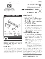
V9580
Бренд: RS Страницы: 4
RF-4755732
Бренд: Renkforce Страницы: 4
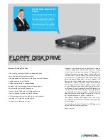
FLOPPY DISK DRIVE
Бренд: Freecom Страницы: 2
IO-FMP220
Бренд: Koutech Страницы: 13
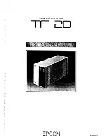
TF-20
Бренд: Epson Страницы: 79
Zip-100
Бренд: Epson Страницы: 23
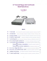
Modular Floppy Disk Drive
Бренд: Fujitsu Страницы: 8
MP-1802
Бренд: Hitachi Страницы: 92
FB-100
Бренд: Brother Страницы: 4
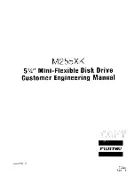
M255XK
Бренд: Fujitsu Страницы: 94
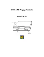
1.44MB Floppy
Бренд: HI-VAL Страницы: 6
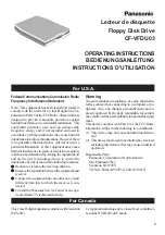
CF-VFD Series
Бренд: Panasonic Страницы: 8
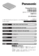
CF-VFDU03U - 1.44 MB Floppy Disk Drive
Бренд: Panasonic Страницы: 16

CF-VFDU03W
Бренд: Panasonic Страницы: 8

MF-68
Бренд: SWTPC Страницы: 21


