background image

Q2 Quickie Construction Manual

The QUICKIE Q2 kit, properly constructed, will reproduce the successful 
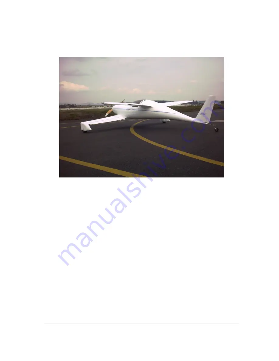
original QUICKIE Q2 designed, and tested by QUICKIE AIRCRAFT CORPORATION. 
QUICKIE AIRCRAFT CORPORATION is not responsible, and makes no warranties, 
express or implied whatsoever, regarding the structural integrity, 
performance, flight characteristics, or safety of the Buyer's completed 
aircraft and its component parts. QUICKIE AIRCRAFT CORPORATION has no control 
and assumes no control over the Buyer's ability to successfully construct and 
test the QUICKIE Q2 AIRCRAFT. Buyer expressly waives any and all claims 
arising from structural integrity, performance, flight characteristics, 
mechanical failures, and safety against QUICKIE AIRCRAFT CORPORATION. Buyer 
acknowledges awareness of the risks of flying a homebuilt aircraft. Buyer 
acknowledges that the FAA must inspect the aircraft at construction intervals, 
as well as the completed project, prior to flight and should work with his 
local FAA representative regarding the construction and licensing of the 
aircraft.

..  

QUICKIE AIRCRAFT CORPORATION reserves the right to make recommended revisions 
in the plans and construction of the aircraft at any time without liability to 
QUICKIE AIRCRAFT CORPORATION, as such revisions or changes may be deemed 
advisable from time to time.


Summary of Contents for Q2 Lite

Page 1: ...IRCRAFT Buyer expressly waives any and all claims arising from structural integrity performance flight characteristics mechanical failures and safety against QUICKIE AIRCRAFT CORPORATION Buyer acknowl...

Page 2: ...L FIN CONSTRUCTION 2 1 8 BASIC FUSELAGE ASSEMBLY 5 3 9 MAIN WING CONSTRUCTION 9 5 10 CANARD CONSTRUCTION 10 5 11 WHEEL PANT TIRE WHEEL BRAKE ASSEMBLY 6 3 12 MAIN WING AND CANARD MOUNTING 3 2 13 CANOPY...

Page 3: ...July and October includes plans changes builder tips options current and future developments and dates and information on future seminars 25 May 1978 Q2 Information Package Provides general informati...

Page 4: ...to any builder who reports this problem Q2 Plans Change Notices Q2PC9 Q2PC10 are mandatory revisions to the Q2 plans Each Q2PC has a number and a publication date along with a description of the chan...

Page 5: ...ENGINE MOUNT INSTALLATION P 16 2 does not indicate the required spacer The material is 4130 steel or mild steel of 1 2 0 0 x 3 8 1 0 The sketch indicates the location of this QEM5 spacer 4 required i...

Page 6: ...cond Q2CSA11 arm can be slid on the outboard end inward with the lead weight projecting forward Reinstall the bolts holding Q2CSA8 in place Locate the Elevator Rigging template and jig the elevator in...

Page 7: ...nd must be adjusted for minimum friction Once the amount of lead weight on each elevator has been adjusted bolt the entire pitch control system together and check for friction excess play and interfer...

Page 8: ...work continues on a set of retrofittable hydraulic disc brakes which may be available as early as October 1981 Those builders not ready to fly before then may wish to wait and decide whether they wish...

Page 9: ...kle assembly on the left side must be attached directly to BS5 because of the proximity of the cable to the left elevator slot foam core The turn buckle for the right side can be mounted in the system...

Page 10: ...Q2 Plans Appendix Page v Q2 Plans Chapter 1 Page 1 1...

Page 11: ...on the inboard position of the main wing Yaw control is provided by a rudder mounted on the vertical fin and is actuated by conventional rudder pedals The pitch and roll capability is provided by a s...

Page 12: ...y the airplane and then ask us if your modification will work we cannot give you an answer without conducting the appropriate tests and totally qualifying the modification This would obviously be quit...

Page 13: ...s 5 Provided a complete kit from one source to eliminate time spent looking for materials 6 Identified the difficult to build items and included them prefabricated and ready to install with the basic...

Page 14: ...e made considerable effort in the Q2 Construction Plans to make the information visible If you do not understand something study the words in the step study the sketches and all related sections views...

Page 15: ...nd them photos and some words on your progress FAA LICENSING PROCEDURES This procedure applies in the U S A only The Federal Aviation Administration FAA has a definite procedure for registering and li...

Page 16: ...gistration fee along with copies of your sales agreement and invoice signed by Quickie Aircraft Corporation Send those things to FAA Registry Box 25082 Oklahoma City OK 73125 5 After you have made a f...

Page 17: ...Q2 Plans Chapter 1 Page 1 3...

Page 18: ......

Page 19: ...ASIC REQUIRED TOOLS Common household butcher knife Coping saw 1 4 drive socket set Small open end wrenches Sandpaper 50 sheets 40 grit 3M Production Paper D wt 50 Sheets 80 grit 3M Production Paper D...

Page 20: ...Set of 1 4 1 2 and 1 chisels wood 1 2 dia 100 counter sink piloted 6 machinist steel ruler X Acto razor saw 3 8 variable speed hand drill Hand broom brush Bench mounted belt sander Stanley surform pla...

Page 21: ...integrity If you insist on making non approved substitutions for replacement and spoilage we insist that you do not call your aircraft a Q2 Quickie Aircraft Corporation will not provide assistance in...

Page 22: ...Quickie Newsletter This section will teach you all of the techniques required to build your airplane show you what special tools you need and how to use them The educational samples that you will bui...

Page 23: ...hen you eyeball it from one end Mark it and hang it on the wall so it doesn t end up as part of a shelf Epoxy Balance Devices which automatically ratio the correct amount of resin and hardener and dis...

Page 24: ...RATIO BALANCE FOR RESIN HARDENER 1 Place both empty cups as shown wet the hardener cup 2 Adjust ballast weight to level mark 3 Fill resin cup with desired amount of resin 1 to 6 oz 4 Add hardener to h...

Page 25: ...CONTINUED ON NEXT PAGE PAGE 3 1 Q2 Plans Chapter 3 Page 3 02...

Page 26: ...he current to obtain a wire temperature which will allow the wire to cut the foam at a rate of one inch every four to six seconds when pulled with a light load less than pound This can be checked with...

Page 27: ...the construction of your Q2 are recent to homebuilding This section is devoted to familiarizing you with the language materials and techniques used in these plans This information is basic to the con...

Page 28: ...rk correctly is important this doesn t mean that it is difficult Two types of glass cloth are used a bi directional cloth 5277BID and a unidirectional cloth 5177UND Use the full part number for orderi...

Page 29: ...CONTINUED ON NEXT PAGE...

Page 30: ...ase or epoxy should be discarded A clean smooth surface is needed for marking and cutting The area used for storing and cutting glass cloth should be separated from the aircraft assembly area because...

Page 31: ...become a household word Unfortunately epoxy is the general term for a vast number of specialized resin hardener systems the same as aluminum is a general term for a whole family of specialized metal a...

Page 32: ...used in sheet metal construction or clamps in woodwork for temporary positioning Five minute is also used in some areas where high strength is not required but here a fast cure will aid assembly Safe...

Page 33: ...tio will cause the epoxy to retain its heat increasing its temperature This results in a faster cure causing more heat This unstable reaction is called an exotherm Exotherm temperatures can easily exc...

Page 34: ...this occurs the epoxy has not cured either due to inadequate time or temperature or bad mixing or bad epoxy MICROSPHERES Microspheres are a very light filler or thickening material used in a mixture...

Page 35: ...poxy no microspheres on the fiberglass surface and micro slurry on the foam surface 3 Refer to the sketch and trowel wet or dry micro in the center of the joint Thus when joined the micro is pushed ou...

Page 36: ...and the metal dull with 220 grit sandpaper and paint pure mixed epoxy no f10x on the metal part BONDO Throughout these plans the term Bondo is used as a general term for automotive polyester body fill...

Page 37: ...that will later be structurally attached to another fiberglass layup Once the dacron is peeled off the surface is ready for another layup without sanding If you do not use peel ply you will have to s...

Page 38: ...is completely fuel proof The urethane used is Urethane 210 or equivalent The white styrene modified urethane foam is used in medium density 4 6 lb ft3 where higher compression strength is required Do...

Page 39: ...CTION Q2 Plans Chapter 3 Page 3 06 CONSTRUCTION TECHNIQUES HOT WIRE CUTTING The airfoil shaped surfaces of your Q2 are formed by hot wire cutting the orange or blue white styrofoam of 2 lb ft3 density...

Page 40: ...sed In general the trailing edge of the wing is the reference Full size template drawings are provided in the plans To make your templates just glue the template drawings to a piece of plywood or shee...

Page 41: ...sions for the correct planform These trim cuts are made using two straight edged trim templates The templates are held against the foam by nails through the template into the foam Enough nails should...

Page 42: ...hem Some rib templates are used several times for both inboard and outboard requiring you to transfer the talking numbers pause marks trim line and waterline to the opposite side of the template Suppo...

Page 43: ...ve notations in the areas where reduced speed cutting is necessary and pause marks where it is necessary to allow the lag to catch up completely The most common hot wire error is wire lag which causes...

Page 44: ...in epoxy are used for temporary foam joints but the hot wire won t cut through these Thus they have to be placed carefully so that the wire doesn t have to pass through them Don t be overly concerned...

Page 45: ...ap foam piece to smooth the surface The foam scrap conforms to the shape of the surface resulting in a very smooth contour Outside contours are roughed out with a sanding block and finished using a fo...

Page 46: ...t the shop is clean before you start Take the recommended health precautions discussed later in detail using gloves or barrier skin cream Get your grubby old clothes on or at least a shop apron Make s...

Page 47: ...cloth is to be applied around and or into a sharp corner you will find the job easier to do if the fiber orientation is at 45 to the corner Don t get depressed if the layup looks like a hopeless mess...

Page 48: ...er handy for spreading around the epoxy The final plies are ambitiously stippled and additional epoxy is applied sparingly When in doubt squeegee it out As you wet out each ply scissor trim to within...

Page 49: ...to use your stippling roller or brush on an area after squeegeeing Some places are not suited to the use of a squeegee and the dry brush or roller must be used to expel the excess epoxy On a given lay...

Page 50: ...n Epocleanse is used to remove the epoxy Both of these products are available Once you are sure your skin is clean wash again thoroughly with soap and water even if your hands were protected with plas...

Page 51: ...ut six hours at 60 degrees and one hour at 90 degrees OTHER SURFACES Surface preparation step 3 of the basic glass layup varies with the material that you are laying up over The layup over foam was co...

Page 52: ...75 Don t undertake a layup if it is pouring down rain outside or if you notice a cloudy blush on the wet epoxy surface or any evidence of whiteness in the epoxy due to moisture RECOGNITION OF A DRY LA...

Page 53: ...where overlaps or thick buildups are done These rough edges should be smoothed as shown using a grinder or sanding block The Dremel Moto Tool or Home Shop Weller is a very versatile tool with many use...

Page 54: ...ithoper project RIVETING A pneumatic riveter is not required The few hard rivets used can be set with a hammer using your vise as backup The pop type rivets are pulled with a low cost hand puller avai...

Page 55: ...s case at the 25 point mark it with the letter A and roll it up to keep dirt out of the fibers When you next unroll it you will probably find that the edges are frazzled As long as you don t reduce th...

Page 56: ...poor adhesion and subsequent failure of the layup TAPES Quite often during the construction of your Q2 you will be asked to use glass tapes to join two pieces together A glass tape is a strip of BID...

Page 57: ...plies during the layup The areas look like air bubbles and are distinctly visible even deep in a cured layup Small delaminations or bubbles up to 2 inch diameter may be filled with epoxy by drilling a...

Page 58: ...he following is a listing of the critical areas the portions of the Q2 that must meet all the inspection criteria 1 Entire canard 2 All portions of the fuselage within 10 of the engine mounts canard a...

Page 59: ...basic rule remove the rejected or damaged area and fair back the area at a slope of 1 per ply with a sanding block in all directions By watching the grain you will be able to count the plies while san...

Page 60: ...the corner and the other where a structural filler is used and glass is bonded to the filler The corner with the glass fibers running completely around it is used where maximum strength is required In...

Page 61: ...a radiused edge Where the glass fibers run directly around the corner a minimum radius of 3 16 inch is required Where the fibers run at an angle to the radius only a 1 8 inch radius is needed CONTINUE...

Page 62: ...is used A simple unsupported glass corner has very poor strength To strengthen this corner a triangle of flox is used to bond the glass plies together The flox corner is done just before one glass su...

Page 63: ...y supported until fully cured Do not hang or support them at each end for long periods as they may creep or slowly deform Store them leading edge down with support in at least three places Your surfac...

Page 64: ...nybody else we abbreviate these as FS BL and WL Fuselage stations FS are used to define the location fore and aft on an airplane To make things easy fuselage station a is generally located near the no...

Page 65: ...ust be finished to a smooth and wave free surface the canard We have found that unless the canard is smooth and wave free serious degradation of performance and flying qualities results This section w...

Page 66: ...between color and surface temperature White has been chosen as the standard color for fiberglass sailplanes to preclude any possibility of excess temperature due to solar heating The same criteria ap...

Page 67: ...uer is easy to work with easily patched and readily polished to a high gloss The enamels and acrylic enamels are low cost and easy to apply however they are not readily repairable if chipped The polyu...

Page 68: ...nd one for medium or fine sanding The spline is an easy tool to use but it may require your close attention at first The spline is always held with handles parallel to the leading edge of an airfoil s...

Page 69: ...fourth step is the application of an ultra violet barrier primer Fifth the final finish paint is applied The following sketches are descriptive of the finishing process and its potential pit falls Th...

Page 70: ...CONTINUED ON NEXT PAGE PAGE 3 15 Q2 Plans Chapter 3 Page 3 16...

Page 71: ......

Page 72: ......

Page 73: ...d start grinding on your composite structure it s like using acid to clean a metal wing spar It must be done carefully Start by determining which areas require micro filler as shown using a flexible y...

Page 74: ...CONTINUED ON NEXT PAGE PAGE 3 16 Q2 Plans Chapter 3 Page 3 17...

Page 75: ...uld be mixed very dry lots of microspheres to save weight Let the micro cure at least 24 hours Sand the micro overfill into contour using a hard sanding block or spline with coarse 36 to 60 grit sandp...

Page 76: ...hesitate to use a second coat of feather fill A well prepared surface generally won t need more than one coat When you have finished contouring the feather fill the surface should be basically smooth...

Page 77: ...for finish paint STEP FIVE FINISH PAINT Follow the manufacturer s directions for the type of finish paint that you have chosen COCKPIT INTERIOR It is not necessary to fill the glass weave although so...

Page 78: ...two fingers 2 inches apart If the surface is a smooth curve between your two fingers the ruler will lay down following the curve with no gaps If the surface is bumpy or wavy the ruler will touch the s...

Page 79: ...s operating limitations normal and emergency operations flying qualities maintenance specifications inspection procedures and initial flight test procedures 2 2 STRUCTURAL APPROACH The basic structure...

Page 80: ...DEFECTS 3 1 VOIDS Interlaminar voids in a new layup may be due to small air bubbles trapped between plies during the layup These void areas look white and are distinctly visible even deep in a cured l...

Page 81: ...wrinkles or bumps along more than 2 inches of chord are cause for rejection in the wings canard and vertical fin particularly on the upper surfaces compression side Disruptions greater than 2 inches r...

Page 82: ...ne The tapered glass edges and surrounding two inches of glass surface must be sanded completely dull Damaged underlying foam should be removed and the void filled with a dry microsphere epoxy mixture...

Page 83: ...nly to the QUICKIE and Q2 structures Design safety factors in excess of three enable somewhat relaxed acceptability criteria compared to other similar structures PAGE 3 20 Q2 Plans Chapter 3 Page 3 20...

Page 84: ...plies are completely wetted but not full of excess epoxy Let the layup cure to knife trim about four hours Carefully mark a 10 inch by 16 inch rectangle and knife trim the layup to that size using a s...

Page 85: ...ong to the top of your work table Shape a piece of green foam as shown Go to your glass cutting area and cut the glass plies shown Lay up two plies of UNI two plies of BID paint the foam with micro sl...

Page 86: ...broom handle or piece of tubing on the work bench and try to break the sample by putting all of your weight on the ends A 200 pounder will stress the sample more than any part of your airplane is stre...

Page 87: ...fore starting on your airplane is a book end It takes three layups to make the book end and involves most of the operations that you will need to learn to build your airplane Cut the 3 blocks of green...

Page 88: ...h it as shown Lay up the first ply of BID as shown Using plain epoxy no micro lay up the other two plies and allow to cure Note how the 45 fiber orientation allows the glass to lay down completely int...

Page 89: ...brush to rough out a depression in the middle of the block Finish smoothing the depression by rubbing it with a scrap of green foam Radius the corners of the depression Blow or brush all of the foam d...

Page 90: ...plies and wipe in a little dry micro You will then find that it will lay smoothly in without voids see sketch This depression is sharper than any in your airplane and is intended to give you a feelin...

Page 91: ...Wait until the second layup is fully cured Remove the 1 inch foam block with a butcher knife and sanding block Remove foam for a 1 4 flox corner and sand the glass surface dull...

Page 92: ...Mix Safe T Pox a small batch of flox and a small batch of micro slurry Fill the corner with flox and slurry the foam Lay up the four UNI plies with the orientation shown...

Page 93: ...und curves flox corner knife trim concave and convex foam carving glass to glass surface preparation and sanding edges So use this experience to your best benefit and spend the curing time studying th...

Page 94: ...r bumps even fill holes or gouges with dry micro immediately before the layup Brush or blow away dust GLASS Always sand completely dull any cured glass surface 36 grit or 60 grit sandpaper Re sand if...

Page 95: ...aighten wrinkles If working alone on a long piece roll the cloth then unroll it onto the surface 5 WET OUT Don t slop on excess resin bring epoxy up from below with a vertical stab of the brush stippl...

Page 96: ...dges by razor trimming the edges at the knife trim stage which is about 3 4 hours after the layup 9 GENERAL INSPECTION Take a good look for dry glass excess resin bubbles and delamination before walki...

Page 97: ...e with 212 volt 6 amp battery chargers or 12 volt car batteries Foam block must be well supported and weighted Templates must be nailed on tight First cut the basic block to size this determines the p...

Page 98: ...bolt AN4 1 4 dia bolt AN509 flush head screw AN525 washer head screw all metal lock nut AN363 1032 AN363 428 plain washer AN960 wide washer AN970 QUALITY CONTROL CRITERIA REPAIRS See the Education se...

Page 99: ...so do a good job in the beginning Template drawings provided for parts made as a sandwich composite glass foam glass should still be made on the hardboard plywood or masonite of 1 4 thickness It will...

Page 100: ...uel tank shape you will heat form two pieces of the 1 4 thick white foam around the templates glass the top main fuel tank surface and finally glass the inside main fuel tank surface after the first l...

Page 101: ...n the inside foam surface Be careful that the main fuel tank doesn t warp and change shape during this process If you have trouble with waves in the center of the tank additional Fuel Tank Profile Tem...

Page 102: ...foam and number them left right and center to identify where they are assembled in the aircraft In airplane talk left is the pilot s left as he sets in the cockpit Fiberglass 1 BID on the inside face...

Page 103: ...d itself As indicated previously the writing on the template drawings can be read when the part is right side up Also the drawings indicate the number of each piece to be made ALUMINUM PARTS On Append...

Page 104: ...bulkheads are made from the 3 B thick white foam You will find full size template outlines on the large Appendix Sheets 1 and 2 On this sheet you will find sketches showing the foam layouts Where two...

Page 105: ...erve space the templates are laid out with the joint between the two pieces as the common line at the top of the template This is the only case in these template drawings where the presentation is not...

Page 106: ...s they may be used later 4 All foam blocks must be weighted down carefully all template level lines must be re checked just prior to hot wiring 5 Hot wire cores at the top of each block first to make...

Page 107: ...e edge of the polystyrene foam This gives the core the proper geometry for assembly into the main wing female jigging templates The aileron cores must be trimmed on either end after hot wiring to 48 l...

Page 108: ...roper geometry upon jigging Next find the extra pieces from the 10 x 24 blocks 2 and face them up to the dimensions shown These two blocks are used for the inboard elevator cores and inboard canard co...

Page 109: ...make the height over 6 0 Note the 0 6 taper dimension is to allow for the proper anhedral angle upon assembly in the canard female jigging templates Take the two canard template BL48 8 and BL15 and re...

Page 110: ...areas are marked save on the sketches Add some additional scrap pieces being careful to obtain proper skew throughout the setup and make the inboard elevator cores The template offsets are necessary...

Page 111: ...you used to make the canard center section core Remember the one we told you to keep and not throwaway The sketch is self explanatory RUDDER AND VERTICAL FIN TRAILING EDGE These two cores are made fr...

Page 112: ...ar to the way that the aileron extends outboard on the main wing only part way WHEEL PANT CORES The wheel pant cores are cut out from the scrap pieces that you now have laying around They needn t be h...

Page 113: ...nts and the oxidation layer on the aluminum Trial fit CS9 to the aileron foam core mix up some micro slurry and then join CS9 to the aileron foam core on a flat surface Use nails to hold the two piece...

Page 114: ...emove the leading edge L E joggle Leave the trailing edge untrimmed until after the aileron is mounted on the main wing so that it can be made to match the trailing edge of the wing The joggle on the...

Page 115: ...Q2 Plans Chapter 6 Page 6 02...

Page 116: ...you will join CS21 to the rudder foam core sand the joints to remove bumps and joqgles layup the bottom skin layup the top skin and finally trim the trailing edge T E after installation on the vertic...

Page 117: ...cover only the construction of the left elevator but the right elevator is a mirror image It is suggested that both elevators be constructed simultaneously Since the elevator has a tapered chord BE S...

Page 118: ...gether with micro slurry insert CSI6 then insert the front foam piece Do not telescope CS16 into the core by pushing it from one end this will cause voids in the bond Instead it should be inserted all...

Page 119: ...s that you learn in this chapter will come in handy on the more complicated structures like the main wing and canard JIGGING THE VERTICAL FIN Construction begins by jigging the vertical fin core on th...

Page 120: ...les can be sanded away Join the vertical fin core to the vertical fin trailing edge core with micro slurry and a few dabs of 5 MIN to hold the two together Since the vertical fin is symmetrical verify...

Page 121: ...laminate the skin you will obtain a glass to glass bond at the vertical fin slot The lamination of the skin and spar caps is very similar to what you have previously accomplished in making the aileron...

Page 122: ...mplates again in the following lamination Check all level lines again and again before completing the jigging The lamination for the other side of the vertical fin is identical to what you previously...

Page 123: ...END OF CHAPTER PAGE 7 2 Q2 Plans Chapter 8 Page 8 01...

Page 124: ...fit The parts should be inspected by the builder for quality control using the Composite Materials Education chapter as a guide In addition if you measured carefully you would find that although the...

Page 125: ...ich is sent to your pre trimmed to rough shape over the forward fuselage Even up the sides by measuring the distance on each side up from the longitudinal fuselage split line and adjusting the canopy...

Page 126: ...vel placed across the longitudinal split line at the firewall attachment point is correct for leveling the fuselage laterally Don t forget that the firewall fits inside the shell The FS120 bulkhead lo...

Page 127: ...CONTINUED ON NEXT PAGE PAGE 8 2 Q2 Plans Chapter 8 Page 8 03...

Page 128: ...ted and upright portions of the Seatback Bulkhead Be sure to bevel the intersect ion The firewall is mounted with 3 BID tapes outside wrapping around the corner which means you will have to radius the...

Page 129: ...ward face of the Seatback Bulkhead with a few dabs of 5 MIN It is permanently mounted with flox and 2 BID tapes on either side lapping onto the bulk head and fuselage a minimum of 1 5 inches and lappi...

Page 130: ...fill the voids prior to glassing with 0 7 inch minimum lapping onto the canopy and a minimum of 1 5 inches lapping on the existing fuselage inside skin Permit the laminations to cure for 24 hours PAG...

Page 131: ...e inside of the seam If you elect to do that later don t forget about it Of course micro slurry is used between the parts Joining the forward fuselage shells is somewhat more difficult because of the...

Page 132: ...the cockpit area is designed around it so be careful of deviations Mark the line with a felt tipped marker on the shells and check for symmetry Use a fine tooth hacksaw blade to carefully cut through...

Page 133: ...sides where the longerons will be mounted Once the canopy frame has been cut out and the longerons bowed statica11y then they should be mounted in the fuselage to increase the strength of the fuselag...

Page 134: ...END OF CHAPTER PAGE 8 5...

Page 135: ...utting to prevent damage JIGGING THE MAIN WING Construction begins by jigging the main wing on the jig table Locate the main wing cores that you have previously hot wired It is not necessary to use ei...

Page 136: ...NOTE See Bottom and Top Main Wing Lamination Drawing for exact sizing of sparcaps A thru M...

Page 137: ...CONTINUED ON NEXT PAGE PAGE 9 1 Q2 Plans Chapter 9 Page 9 02...

Page 138: ...CONTINUED ON NEXT PAGE PAGE 9 2 Q2 Plans Chapter 9 Page 9 03...

Page 139: ...everything properly The next step is to join the foam cores together with micro slurry after verifying that the core fit is within 1 16 Check recheck and re recheck each core level line and alignment...

Page 140: ...ements indicated above should be made along a WL not along the contour of the wing SHOULDER HARNESS INSERT INSTALLATION Each shoulder harness is installed in a Y fashion to the lower main wing Prior t...

Page 141: ...ird individual mixes epoxy while the other two do the lamination To summarize the lamination first you will laminate the wing skin which is 2 plies of UNI at 45 degrees to the main wing T E and then y...

Page 142: ...around the corner and down to the bottom of the shear web so that the shear web has two plies of UNI at 45 degrees to the T E and at 90 degrees to each other Trim all edges like you did on the first p...

Page 143: ...laminations But if your like everyone else you won t be able to resist making that jigging table into a main wing for your Q2 as quickly as possible LAMINATING THE TOP SKIN AND TOP SPAR CAPS Build a...

Page 144: ...ace See Preparing The Main Wing Cores For Glassing you are now ready to laminate the top main wing skins and top spar caps Do it similarly to the bottom lamination The skin is the same two UNI at 45 d...

Page 145: ...d over the two SH1 s when you performed the BOTTOM skin and spar cap lamination Now is the time to drill and tap each SH1 with a 1 x 28 tap for a AN4 bolt later The sketch shows the complete assembly...

Page 146: ...rmine where to trim the outboard aileron slot foam cores Since each elevator was made 48 long measure 48 plus 1 inch for aileron fuselage clearance from your first mark outboard and place another mark...

Page 147: ...ores top and bottom being sure to achieve at least 0 4 of glass to glass bond and lapping up onto the main wing at least I Note that the sketch in the CANARD chapter calls out dry micro fill if requir...

Page 148: ...3 washers and the 2 AN363 428 nuts There must be a minimum of 0 6 from the AN960 4 washer inboard to the end of the QCSM5 stud This is to require the aileron to be moved inboard at least 1 4 before i...

Page 149: ...ct the CS5 and CS12 push pull tubes in order to have a functioning aileron control system This section is very important so take your time and read through the entire section several times prior to st...

Page 150: ...here to assist bonding of the phenolic to the structure They are NOT lightening holes Find Q2CSA4 2 Make CSll 2 from 0 625 O D X 0 065 wall 4130 steel tubing The length of CS11 which can be critical f...

Page 151: ...Q2 Plans Chapter 9 Page 9 07 The following procedure was developed to help you get the ailerons mounted without binding with the proper clearances and with the ability to get them off again...

Page 152: ...e tube looks like a shiskabob doesn t it 3 Slip C57 on the end of Q2C5A4 4 What follows is a very qualitative fitting process Using at least two people dry fit C510 C56 and C57 firmly against the main...

Page 153: ...ounted so that they cannot be accidentally broken off while in service 8 Once the laminations in step 7 have cured you are ready to drill in the aileron assemblies Find your aileron rigging template r...

Page 154: ...CONTINUED ON NEXT PAGE PAGE 9 8 Q2 Plans Chapter 9 Page 9 09...

Page 155: ......

Page 156: ...ores begin at the outboard end of each CSI0 and run outboard to the main wing tip When originally hot wired they were made longer than necessary on the inboard end so fit each one into position and tr...

Page 157: ...u did on the aileron If you are careful you may be able to accomplish the laminations with the wing jigged vertically to save time however beware of epoxy runoff yielding dry lamination An alternative...

Page 158: ...ou have gained in completing the main wing for your Q2 should allow you to construct the canard in the same amount of time You may wish to reread the chapter on the MAIN WING to review the procedures...

Page 159: ...retched spanwise with a weight attached at either end may be helpful in establishing and keeping the straight line Now begin to trial fit the five canard cores into position Be careful in handling the...

Page 160: ...CORES FOR GLASSING At this point the canard cores should be jigged on your jigging table upside down 5 minuted and bondo ed in place and able to take a direct hit from a 88 mm howitzer without budging...

Page 161: ...PAGE 10 2 Q2 Plans Chapter 10 Page 10 03 PAGE 10 3...

Page 162: ...nce you have had on the main wing you should be within 10 of the maximum laminating speed that you will ever obtain Work with one piece of cloth at a time and with small batches of slurry and epoxy Un...

Page 163: ...you must rise up to the occasion and concentrate on squeeging each spar cap well to avoid excess epoxy which leads to excess weight Use extra epoxy very sparingly on the last spar cap Every other spar...

Page 164: ...ketch is to layup 1 UNI first then 2 BID and then 1 UNI on top for the final ply Take your time and make the fibers straight The 2 BID are laminated at 45 degrees to the spanwise direction Knife trim...

Page 165: ...the center section core Remember that the flox corners are much harder than the foam surrounding them so go easy You must really prepare the top canard surface well and remove all bumps joggles and ot...

Page 166: ...the T E and down the shear web trim every other one off at the T E Peel Ply the shear web and all joints Don t touch the canard for at least 48 hours Before removing the lumber bondo a level board at...

Page 167: ...PAGE 10 5...

Page 168: ...slot foam core within 1 2 of the top edge and continues all the way outboard to the end of the outboard elevator slot foam core on the right side of the aircraft Let the Nylaflow tubing extend about 4...

Page 169: ...xy and get down to the glass Spend some time looking at the surfaces getting the best alignment that you can When everything is ready laminate 2 BID at 45 degrees to the canard shear web on the elevat...

Page 170: ...assembly Remember there must be a minimum of 0 6 from the AN960 4 washer inboard to the end of the QCSM5 stud so that the elevator must be moved inboard at least 1 4 before it falls off the QCSM5 stud...

Page 171: ...e CS16 elevator torque tube while remaining perpendicular to CS16 This is to allow assembly and disassembly of the elevator Probably you will have to open the routed slot up to about 0 6 wide At the s...

Page 172: ...f the QC5M3 stud During this movement the C517 hinge remains where it was since it was permanently attached to the canard between a sandwich of C518 inserts during assembly Do you understand Good read...

Page 173: ...drill ed out These are non critical on diameter but must be there to assist bonding of the phenolic to the structure They are NOT lightening holes Find Q2C5A8 Make C520 from 0 625 0 0 x 0 065 wall 413...

Page 174: ......

Page 175: ...517 e515 and C514 Please do one thing at a time The arm on Q2C5A8 should be at approximately BLOO 5 When the complete elevator assembly fits well and rotates freely mix up some 5 MIN with flox and tem...

Page 176: ...CONTINUED ON NEXT PAGE PAGE 10 9 Q2 Plans Chapter 10 Page 10 10...

Page 177: ...d CS20 overlap into the elevator reducers a minimum of 1 8 and that both are pushed up tight onto the universal joint Now drill in very carefully the four bolts that fasten Q2CSA8 CS20 universal joint...

Page 178: ...can obtain equal results by painting the canard black with primer and setting it in the bright sun to effect the post cure If you desire you may want to finish the canard up to the primer stage befor...

Page 179: ...T THE CANARD TO GET TOO HOT It is not necessary to post cure any other structure on your aircraft END OF CHAPTER PAGE 10 10 Q2 Plans Chapter 11 Page 11 01 WHEEL PANT TIRE WHEEL BRAKE ASSEMBLY INTRODUC...

Page 180: ...until they are cured Once the combination has cured lay it face down on the table with LG2 against the table Laminate the plies shown in the sketch Now you are ready to flag the UNI stiffener over th...

Page 181: ...point you should have a sandwich with one LGI as the core one LG2 as the outboard face and one LG2 as the inboard face Allow the assembly to cure Next the two LG4 inserts must be bonded into position...

Page 182: ...ing of the pant where it fits against the canard is necessary The bevel is approximately 1 to 10 Note that the LGI core is sized to fit at BL93 so don t modify the inboard edge very much Once the asse...

Page 183: ...od prior to glassing to avoid using considerable flox to fill the voids Peel Ply the lamination When the lamination is cured mount the wheel pants with flox to the canard being sure to achieve good fl...

Page 184: ...Lap up onto the canard a minimum of 1 5 inboard of the contouring and use a minimum of 1 overlap wherever else you overlap the cloth After this layup has cured remove the lumber jigging from the insi...

Page 185: ...PAGE 11 2...

Page 186: ...re will clear the side of the fuselage and that the entire rudder pedal brake pedal assembly will not interfere with any of the fuselage structure Assemble the rudder pedals Q2CSA9 and the brake pedal...

Page 187: ...CONTINUED ON NEXT PAGE PAGE 11 3...

Page 188: ...piece of Nylaflow tubing to a second pulley cantilevered off the shear web of the canard From there it travels outboard through the Nylaflow tubing buried in the elevator slot foam core BS3 is a plywo...

Page 189: ...m into the nutplate Assemble the pulley combination as shown Next trial fit the assembly against the canard shear web removing foam and the canard shear web glass as necessary so that the cable will n...

Page 190: ...s to prevent the cable form slipping off the pulley and fouling the system A sample sketch of a pulley guard is included for your reference they should fit as closely as possible to the outside diamet...

Page 191: ...tside faces of the whee1pant measured at the axle hole measure carefully Assemble the QBSM2 spacer between the brake drum and the brake shoe Note that both the spacer and brake shoe fit down into the...

Page 192: ...CONTINUED ON NEXT PAGE PAGE 11 5...

Page 193: ...after the brake drum has been clocked if necessary to allow the brake cable to pass through the cable guide then locate the anti torque AN3 15A bolt as shown You must remove foam and place a 1 square...

Page 194: ...the aileron system on the main wing you will notice that the inboard phenolic bearings and linkages interfere with the FS94 bulkhead as you attempt to install and fit the main wing onto the fuselage...

Page 195: ...meet upon assembly Verify good squeeze out of the flox upon assembly Recheck all level lines and alignment Permit the flox to cure prior to attaching the BID tapes shown Two BID tapes are used everywh...

Page 196: ...PAGE 12 1...

Page 197: ...that you use the axle holes as the reference Verify that the centerline of the canard is at BLOO Be careful that you do not remove a part of your main fuel tank while clearancing the canard You shoul...

Page 198: ......

Page 199: ......

Page 200: ...PAGE 12 2...

Page 201: ...E SHELL If you have decided not to make your Q2 trailerable you should now complete the closeout of the fuselage by permanently attaching the forward and aft fuselage shells at the fuselage cut line o...

Page 202: ...es shown on the outside of the skin after you have sanded dull the existing glass Note that the three tapes have the following widths 5 4 and 3 and that the orientation should be at 45 degrees to the...

Page 203: ...for knife trimming CANOPY FRAME STIFFENERS Three stiffeners will be fabricated One each will be installed on each side of the canopy frame longitudinally and the third will be installed transversely...

Page 204: ...a good fit The two stiffeners one on each side fit out board to the outside skin line as shown This will require removing a portion of the canopy frame as indicated on the sketch There should be an a...

Page 205: ...r is placed transversely at the aft canopy bulkhead Ideally this third stiffener should rest on the top of each side stiffener and on the bottom of the aft canopy bulkhead If necessary a small piece o...

Page 206: ...PAGE 13 1 Q2 Plans Chapter 13 Page 13 02...

Page 207: ...s important to remember that the hinge must be oriented to provide the best compromise for opening and closing of the canopy Some trimming of both the fuselage outboard skin and canopy frame outboard...

Page 208: ...ome gray tape around the canopy frame cutout on the upper forward fuselage to protect the structure Next laminate 4 BID around the cutout with a minimum width of 2 Multiple pieces may be used to make...

Page 209: ...PAGE 13 2 Q2 Plans Chapter 13 Page 13 03...

Page 210: ...ed down tight when the AN525 10R10 screw is slipped into the hole in C2 Drill in C2 while inside the cockpit The canopy latch is very important With some foam sealing material with adhesive backing in...

Page 211: ......

Page 212: ......

Page 213: ...PAGE 13 3...

Page 214: ...n on the left longeron where each cutoff bolt contacts the longeron upon closing Drill a 5 16 hole at each location grease up the bolt and surrounding area with Vaseline fill the hole with flox and cl...

Page 215: ...ight The flight characteristics of the Q2 with a partially open canopy have not been explored A safety latch is assembled to prevent this potentially lethal situation from developing Make sure that yo...

Page 216: ...END OF CHAPTER PAGE 13 4...

Page 217: ...e vertical fin can fit snugly against that bulkhead Use a plumb bob hanging from the trailing edge of the top of the vertical fin with the fuselage leveled laterally to verify that the vertical fin is...

Page 218: ...cure with its length parallel to the aft top fuselage line and that it is not crooked laterally PAGE 14 1 Q2 Plans Chapter 14 Page 14 02...

Page 219: ...he QTW5 fork as shown using the QTWMI axle and AN3 24A bolt The next task is to mount the entire tailwheel assembly to the tailspring Start by leveling the fuselage laterally and then trial fit QTW3 o...

Page 220: ...er torque tube CS23 is the lower rudder phenolic bearing CS23 is bonded to the vertical fin foam core with liberal quantities of flox generating good squeeze out Q2CSAI0 is the rudder bell crank which...

Page 221: ...PAGE 14 2 Q2 Plans Chapter 14 Page 14 03...

Page 222: ...the rudder to provide tension on the cables at all times Cable attachments should be accomplished with no weight on the tailwheel and with the rudder and tailwheel in the neutral position Use the rudd...

Page 223: ...a Bond in with Flox the 1 x 1 X 1 4 mild steel plate and then laminate 2 BID over the entire depression overlapping a minimum of 1 onto the inside bottom fuselage skin Once that lamination has cured m...

Page 224: ...m the aircraft Three baffles are used one spanwise baffle about 18 wide and two longitudinal baffles that extend from the landing edge of the fuel tank to within 4 inches of the trailing edge of the f...

Page 225: ......

Page 226: ...epoxy into a carved urethane foam float nominally 1 diameter by 1 25 high This float assembly will float up and down with the fuel level It rides inside a clear PVC pipe tube that you will calibrate w...

Page 227: ...CONTINUED ON NEXT PAGE PAGE 14 4 Q2 Plans Chapter 14 Page 14 05...

Page 228: ...o notch the forward lower edge of the main fuel tank at BLOO so that the fuel line tubing will exit the tank there Next mix up both pure epoxy and flox Paint pure epoxy liberally on all exposed areas...

Page 229: ...ed for the lamination of 7 BID over it between the plywood and the fuselage skin use epoxy The 0 7 MIN overlap onto the fuselage is very important as is making sure that the glass does not turn any sh...

Page 230: ...CONTINUED ON NEXT PAGE PAGE 14 5 Q2 Plans Chapter 14 Page 14 06...

Page 231: ...laminate 3 BID around the plugs up onto the previous 7 BID lamination with a minimum overlap Finally install the seatbelts themselves The extrusion length for both inboard and outboard pieces is a no...

Page 232: ...sole vertical pieces Remember that the glassed side of those pieces is the side not visible after assembly i e the side nearest BL00 Two cutouts will be necessary for the seatbelts to clear the pieces...

Page 233: ...duce finishing weight later Both the side consoles and the center console should be assembled so that each top piece is level when in place This will be useful later for leveling your aircraft for ins...

Page 234: ...til all cutouts for instruments radios and equipment have been made However at this time you may elect to make the small sub panels that extend from the bottom of the instrument panel to the top of ea...

Page 235: ...Side view of baffle installation Lower Bottom view of baffle installation CONTINUED ON NEXT PAGE PAGE 14 7 Q2 Plans Chapter 14 Page 14 08...

Page 236: ...portant that the bolt tighten down on the spacer not QCSA1 to allow the stick to pivot freely Find the QCS3 spacer material and cut it into two pieces Also find the three phenolic bearings CS1 and CS4...

Page 237: ......

Page 238: ...CONTINUED ON NEXT PAGE PAGE 14 8...

Page 239: ...the pilot for better stick hand geometry CS5 CS12 and CS13 are made from 1 2 O D x 0 035 wall 2024T3 Aluminum tubing The proper lengths will have to be determined upon installation Don t forget the le...

Page 240: ...PAGE 14 9...

Page 241: ...g A AN931 6 10 grommet is bonded to one of the TRl phenolic bearings both of which are bonded to the vertical side pieces of the center console in order to provide friction in the system This is very...

Page 242: ......

Page 243: ...PAGE 14 10...

Page 244: ...together permanently if you do not desire to make your Q2 trailerable EXTERIOR LAMINATION Begin by jigging the two shells together and checking for a good fit Some sanding may be required for a flush...

Page 245: ...ches that only the area around each fastener location is affected If the FS94 bulkhead interferes with the lower 3 locations slot the FS94 bulkhead as needed and then replace the materials A pad of BI...

Page 246: ...PAGE 15 1 Q2 Plans Chapter 15 Page 15 02...

Page 247: ...h against the forward fuselage shell using a few dabs of Bondo By shining a light inside the fuselage at each fastener location in order to see each FC1 drill in the 12 holes 10 locations for the K100...

Page 248: ...isconnect the cables remove one of the AN3 5A bolts from each side In practice to remove the rear fuselage remove the 10 screws in the aft fuselage shell Next pull the forward and aft fuselage shells...

Page 249: ...END OF CHAPTER PAGE 15 2 Q2 Plans Chapter 16 Page 16 01 ENGINE INSTALLATION...

Page 250: ...ck the Q2EM1 to the firewall and then drilling the 4 0 19011 diameter holes per Q2EM1 through the firewall Temporarily mount the EM2 backup plate as shown using some AN3 bolts so that the engine may b...

Page 251: ...ions are rather critical so follow them closely Use a few dabs of 5 MIN to hold the jigsaw pieces together and laminate 1 BID on both the inside and outside of the box Enlarge the previous cutout in t...

Page 252: ...ed over the fiberfrax However the aluminum sheet does not need to be placed over the fiberfrax protecting the magneto starter box you may choose to use 2 layers of fiberfrax wherever a sheet of alumin...

Page 253: ...er with the mounting holes pre9rilled Make EM3 from a piece of 0 25 thick 606IT6 Aluminum A full size pattern is provided Use the predrilled propeller to drill the six bolt holes in the EM3 The propel...

Page 254: ...PAGE 16 2 Q2 Plans Chapter 16 Page 16 03...

Page 255: ...l be when mounted on the firewall It is necessary to do only one half of the cowling at a time Next using grey tape protect two inches of the inside cowling skin and 2 of the template inside surface a...

Page 256: ...is a trial and error operation By fitting the spinner to the crankshaft flange you can determine the necessary cowling length to allow only a 1 16 gap between cowling and spinner Obviously the cowlin...

Page 257: ......

Page 258: ...PAGE 16 3 Q2 Plans Chapter 16 Page 16 04...

Page 259: ...can now be cut into the cowling They are nominally each 3 5 x 6 5 in size with a 3 8 radius using Bondo around the lip A sketch is included for reference COWL FLAP CONSTRUCTION In order to improve th...

Page 260: ...flap with 2 BID Allow room for the cowl flap to open up to 3 0 when making these side pieces Carefully cut out the cowl flap from the lower cowling Smooth up all rough edges A short piece of the MS20...

Page 261: ...s using an approximately 4 spacing The nutplates are secured using AN426 3 5 rivets Take time to accurately mount the cowling halves and you will be rewarded with an excellent fit PAGE 16 4 Q2 Plans C...

Page 262: ...ble Throttle cable rivet a piece of the 3 4 x 3 4 X 1 16 aluminum angle to the oil cooler mount as shown using BSP42 rivets Don t rivet through the oil cooler Then attach the cable guide and install t...

Page 263: ......

Page 264: ...PAGE 16 5 Q2 Plans Chapter 16 Page 16 06...

Page 265: ...cooler Once having passed through the oil cooler this air mixes with the spent cylinder fin air to exit through the cowl flap Aluminum with an 0 032 thickness is the primary baffle material Approxima...

Page 266: ......

Page 267: ...sengers legs The carburetor receives fuel by gravity feed from the header tank The header tank is filled from the main fuel tank by an electric fuel pump with a manual fuel pump as a backup An overfil...

Page 268: ...er and mark the location on the outside fuselage skin where the fuel filler door must go Carefully cut out a door and save it for later Next make a recess for the fuel cap from 1 4 white foam and fibe...

Page 269: ...passenger s feet will clear the header tank The large sump is a simple rectangular box The upper portion of the header tank is curved to fit within the fuselage This section must be custom fitted to e...

Page 270: ...oam One BID on either side of the foam is used when assembling the header tank The laminations that will see gasoline should be made slightly wet to minimize leakage PAGE 17 1 Q2 Plans Chapter 17 Page...

Page 271: ...line from the main fuel tank and the feed line from the engine should be made from 1 4 0 0 Aluminum tubing Allow the tubing to extend out from the header tank about 6 inches Use liberal amounts of flo...

Page 272: ......

Page 273: ...PAGE 17 2...

Page 274: ...gement of clear plastic tubing is used to create a sight fuel gauge It is floxed in place at the top and bottom of the fuel header tank and then run aft through the instrument panel into the cockpit w...

Page 275: ...re it will probably be necessary to fabricate an extension on the fuel valve handle such that the fuel valve can be located near the firewall in order to reduce the length of the fuel line to the carb...

Page 276: ...END OF CHAPTER PAGE 17 3...

Page 277: ...instrument panel removable small tabs can be fabricated These tabs would be bonded to the fuselage and the instrument panel bolted to them Otherwise permanently mount the instrument panel with BID ta...

Page 278: ...it does not interfere with baggage or passengers It is recommended that it travel down the center console before reaching the instruments The pitot system must be leak checked Have one individual wat...

Page 279: ...END OF CHAPTER PAGE 18 1...

Page 280: ...tional information is provided for wiring the more popular optional equipment items A separate schematic details hooking up the magneto switches and tachometer The panel ground bolt is simply a AN3 7A...

Page 281: ...12 v 18 AH battery It is advisable to wait until a weight and balance has been performed see the Q2 Pilot s Manual prior to locating the battery in order to use it as ballast to achieve the desired ce...

Page 282: ...velop a pleasing and efficient shape but at this stage of the construction you will be up to it AILERON FILLETS The aileron fuselage junction should be filleted using scrap foam and 1 BID Each fillet...

Page 283: ...Use scrap foam and 1 BID to create a fillet similar to the one shown in the picture ELEVATOR INBOARD FILLETS At the elevator fuselage junction a more complicated fillet will improve performance Since...

Page 284: ......

Page 285: ...r 20 Page 20 02 CANARD FUSELAGE FAIRING At this point their should be a noticeable and ugly gap under the fuselage where the canard and fuselage meet A fairing should be made out of scrap foam and 1 B...

Page 286: ......

Page 287: ...tip of the vertical fin VERTICAL FIN ATTACHMENT Previously you mounted the vertical fin to the bottom of the fuselage Now is the time to permanently attach it to the fuselage and create a pleasing fi...

Page 288: ......

Page 289: ...Fabricate a round tube by laminating 4 BID around a bottle such that the tube will slip over the end of the alternate air source Don t forget to use Vaseline on the bottle so the lamination can be re...

Page 290: ...llustration shows a simple shock cord arrangement The cable is sized so that the canopy will remain open with tension against the shock cord This will require the canopy to be open approximately 90 de...

Page 291: ...ide of the fuselage must be installed prior to first flight A simple shape and recommended location is shown in the sketches To exhaust the cockpit air a hole could be cut in the tailcone or else an e...

Page 292: ...e bearing through the hole but do not go all the way through and make two pieces The lower half of TS 1 is bonded with resin to the end TS 1 bearing already mounted Do not bond the top half or the sys...

Page 293: ...n traveling from the cylinders to the exit the exhaust system will enter and exit the baffling These holes must be closed up to prevent air leaks and consequent reduction in cooling Also the warm exha...

Page 294: ...u will be visiting Q2 GEOMETRY On the following sheet is a three view of the Q2 On it has been indicated the important aerodynamic and geometric references These have been expressed in terms of your o...

Page 295: ...Congratulations on completing your very own Q2 PAGE 20 4...

Page 296: ...Q2 Plans Chapter 20 Page 20 05...

Page 297: ......

Page 298: ...PAGE 20 5 END Document originally scan copied by Dan Yager Formatted into MS Word and Adobe pdf by QDF_Files To see embedded drawings and photos at higher resolutions view at 200 or more...

Page 299: ......

Reviews: