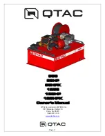
background image


Page | 1 


85S 

85HP 

85HPK 

125S 

125HP 

125HPK 

Owner’s Manual 

QTAC is a division of MTECH, Inc.


1072 Marauder, Suite 210


Chico, CA 95973 

1.888.797.5100


www.qtacfire.com


Summary of Contents for 85HPK

Page 1: ...Page 1 85S 85HP 85HPK 125S 125HP 125HPK Owner s Manual QTAC is a division of MTECH Inc 1072 Marauder Suite 210 Chico CA 95973 1 888 797 5100 www qtacfire com...

Page 2: ...Tank Water Supply 10 Starting the Engine 11 DRAFT PROCEDURES 11 Drafting From an Auxiliary Water Source 11 Connecting the Draft Hose 11 Drafting to Fill the Water Tank 12 Pumping While Drafting From a...

Page 3: ...TING YOUR QTAC 18 The Pump Engine Will Not Start 18 The Pump Will Not Build Water Pressure 18 Water Will Not Discharge From The Discharge Hose 19 The Pump Engine Runs Erratically 19 TECHNICAL SPECIFIC...

Page 4: ...C Figure 1 Tank Components 1 Discharge Hose Rack Reel 5 Water Tank Site Gauge 2 Foam Cell Optional 6 Water Tank Mounting Flange 3 Water Fill Tower 7 Water Tank Drain Port 4 Grab Handle 1 7 2 5 4 3 6 7...

Page 5: ...the Open Position 1 Pressure Gauge HP units only 5 Draft Hose Port 2 Pump Primer Port 6 Pump Drain Port 3 1 NPSH Aux Discharge Valve 7 1 Pump to Reel Valve 4 1 Pump to Tank Valve 8 Tank to Pump Valve...

Page 6: ...Page 6 Figure 3 Pump Engine Components 1 Fuel Fill 5 Oil Fill 2 Engine Throttle 6 Engine Switch 3 Carburetor Choke 7 Pull Starter 4 Fuel Shut off Valve 2 3 4 1 5 6 7 1 2 3 4 5 6 7 85HP 125HP 85S 125S...

Page 7: ...ter in your QTAC to maintain a GVWR under the limit of your vehicle General QTAC Mounting and Fastening Figure 4 Mounting Options Ensure that your QTAC unit is secured to the carrying vehicle Two main...

Page 8: ...you are securing your QTAC is an approved loading area for your ATV or UTV Ensure that the weight of your QTAC does not exceed the maximum recommended weight of the ATV or UTV loading area to which y...

Page 9: ...s Figure 3 Item 5 as needed fill the pump engine with fuel and oil as specified in the engine manual that came with your QTAC For more information see the Pump Operation Manual and the Honda Owner s M...

Page 10: ...H Discharge should be fully closed Figure 2 Item 3 2 Start the engine see next page 3 Water can now be discharged through the reel line To operate the 1 NPSH discharge see page 13 CAUTION During pumpi...

Page 11: ...and decrease the choke until it is no longer needed The output of the pump is regulated by how much throttle is applied as well as the shut off at the nozzle and the pump to tank return DRAFT PROCEDUR...

Page 12: ...e 2 Item 4 5 Start the engine see Page 11 and increase the throttle setting until you see water entering the draft hose and being pulled into the pump head 6 Monitor the water level using the water le...

Page 13: ...etting until you see water entering the draft hose and being pulled into the pump head 6 Use the hose reel discharge nozzle or 1 NPSH discharge line to carry out suppression operations To Supply Water...

Page 14: ...4 GETTING TO KNOW YOUR ATP FOAM KIT Figure 5 Typical ATP Foam Plumbing 1 Foam Cell Tank 2 Vented Lid 3 Foam Supply Valve 4 Proportioner Pressure Valve 5 Foam Proportioner 6 Supply Hose Strainer 1 2 3...

Page 15: ...llow a slight flow 6 Close the 1 Pump to Tank Valve to stop the introduction of foam concentrate into the water tank Figure 2 Item 4 Remember that if this valve is closed a discharge must be open to p...

Page 16: ...tion Manual for additional details NOTE If your QTAC will be subjected to below freezing temperatures ensure that all water is drained from the water tank pumping system and hoses Store with all valve...

Page 17: ...til all foam has been displaced SERVICING YOUR QTAC Cleaning Your QTAC Your QTAC water tank is best cleaned with plain water If additional cleaning power is needed a small amount of dish or car washin...

Page 18: ...pump engine is running and operating at a sufficient speed Ensure that there is sufficient water in the water tank There should be enough water in the water tank so that the water level is visible in...

Page 19: ...off valve is open Ensure that the discharge hose nozzle is open The Pump Engine Runs Erratically Ensure that the engine has adequate fuel Low fuel levels and operation over rough and or sloping terra...

Page 20: ...t single Tank to Pump 1 1 2 NPT Gated Tank to Pump Draft Hose Port 1 1 2 Camlock 85HP 85HPK Tank Body Fully welded top grade Copolymer Polypropylene MTECH PolyToughTM construction Delivery Hose 3 4 in...

Page 21: ...on Delivery Hose 3 4 inch x 50 feet industrial grade rubber standard Delivery Nozzle Brass ball valve shut off with fully adjustable brass nozzle Maximum Tank Capacity 125 US gal 473 2 L Pump Type Kos...

Page 22: ...red under the warranties below WHAT IS WARRANTED All parts of any Product are warranted for a period of 12 months with the warranty term beginning on the date Product is delivered to Purchaser Note th...

Page 23: ...ance or freedom from defect of Product covered by this warranty IMPLIED WARRANTIES OF MERCHANTABILITY AND FITNESS FOR A PARTICULAR PURPOSE TO THE EXTENT APPLICABLE SHALL BE LIMITED IN DURATION TO THE...

Reviews: