1
QLG1 GPS Receiver kit
1. Introduction
Thank you for purchasing the QRP Labs QLG1 GPS Receiver kit. This kit will provide a highly sensitive,
highly accurate GPS receiver module, using the popular MediaTek chipset. This chipset features high
sensitivity (as good, or better, than any other popular chipset) and an extremely accurate 1pps time pulse
(10ns rms). The kit features provide a number of advantages compared to using a ready-built GPS
module:
1) A kit
– fun and educational to build – easy construction with no SMD components
2) High sensitivity: the large ground plane area provides an additional 7.5dBic of antenna gain,
compared to a typical patch antenna arrangement in which the PCB is the same size as the patch
3) Built-in patch antenna, or the ability to connect your own external antenna via SMA if you wish
4) Hobbyist-friendly, 0.1-inch pitch connections
5) Three on-board LEDs provide a visual indication of what is going on
6) Proper 5V level conversion, no need for any pull-up resistors
7) Direct connection to QRP Labs kits by shielded cable, no need for pull-ups or capacitors
2. Antenna
The QLG1 GPS receiver kit can be built with two antenna options: either an on-board patch antenna, or an
externally mounted active antenna (with SMA connector). The module can supply a regulated voltage
suitable for powering the external antenna. The external antenna option may be useful if you wish to
mount the antenna separately to the module; furthermore active external antennas typically provide the
highest receive sensitivity. This may be useful in particularly challenging locations. However, the supplied
custom-tuned patch antenna is already highly sensitive and will be suitable for most situations.
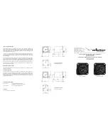
Antenna gain
This chart of antenna gain vs size of the
square ground plane dimension, is extracted
from the manufacturer’s datasheet.
The QLG1 PCB is sized 3.6 x 2.5 inches (91
x 64mm). The right hand side of the PCB is
used for the voltage regulator and level
converter circuits. In this way, the patch
antenna is mounted on the reverse of the
PCB, in the middle of a virtually un-
interrupted ground-plane 64 x 64mm. This is
indicated on the chart by the red line. You will
note that it provides 7.5dBic gain over a more
typical 30 x 30mm0sized ground-plane. This
is an important feature of the QLG1 kit, providing high sensitivity!