Q Imaging OptiMOS Series, User Manual
The Q Imaging OptiMOS Series is an advanced camera system designed for precision imaging. Unlock its full potential by accessing the User Manual, available for free download on our website. Learn everything about this product, including its features and functionalities, and elevate your imaging experience with ease.
Share
Download


Reviews:
No comments
Related manuals for OptiMOS Series

C3
Brand: UMAX Technologies Pages: 20

PG-6100
Brand: Pantech Pages: 87

Z9
Brand: Xblitz Pages: 64

CAM-1000
Brand: Dakota Digital Pages: 8

INHA515 (DVM1500)
Brand: Velleman Pages: 41

DS-2CD2065FWD-I
Brand: HIKVISION Pages: 6

Guardian App Cam 26
Brand: Uniden Pages: 9

CarCam
Brand: A-rival Pages: 38

NCP-DVRGPSWIFI
Brand: NanoCam Plus Pages: 48

Spot-Pointer 139917
Brand: Hama Pages: 51

Minolta VECTISS100
Brand: Minolta Pages: 45

DF-1020
Brand: LENCO Pages: 15

XDS-1078-A9
Brand: IAdea Pages: 2

Camera 335B
Brand: Dukane Pages: 32
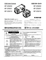
KP-D5000
Brand: Hitachi Pages: 54
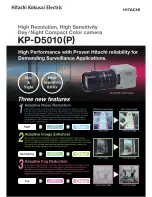
KP-D5010
Brand: Hitachi Pages: 2

28537
Brand: Rollei Pages: 60

WV SCP-2270H
Brand: Samsung Pages: 1


