background image

P

X

-1C

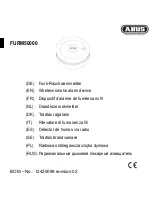
Funk-Rauchwarnmelder

Smoke Alarm Device with Radio Link

Betriebsanleitung

Operating Manual

Summary of Contents for PX-IC

Page 1: ...PX 1C Funk Rauchwarnmelder Smoke Alarm Device with Radio Link Betriebsanleitung Operating Manual ...

Page 2: ...ir freuen uns dass Sie sich für unser Produkt entschieden haben und danken Ihnen für IhrVertrauen Die vorliegende Betriebsanleitung enthält Informationen und Hinweise zur sicheren Montage Inbetriebnahme Einrichtung und Instandhaltung sowie zum einwandfreien Betrieb des Funk Rauchwarnmelders Die Betriebsanleitung soll die Zuverlässig keit sowie die Lebensdauer erhöhen soll Gefahren und Ausfallzeite...

Page 3: ...triebsanleitung ist ein wichtiger Bestandteil des Rauchwarnmelders und muss in der Nähe des Montageortes stets griffbereit aufbewahrt werden 1 5 Verwendete Symbole In der Betriebsanleitung werden im Text unterschiedliche Kennzeichnungen und Symbole verwendet Diese sind nachfolgend erläutert Warnsymbol in Warnhinweisen Zusätzliche Informationen und Hinweise 1 Nummerierte Handlungsschritte f Symbol ...

Page 4: ...ewalteinwirkung auf das Gerät welche bewirkt dass das Gerät zwar äußerlich unbeschädigt jedoch im Gehäuseinneren z B Elektronik beschädigt ist Kontamination Wenn das Gerät äußerlich und oder innerlich durch Anhaftungen kontaminiert übermä ßig verschmutzt ist wird damit der Verlust jeden Garantie Anspruches verbunden Als Kontamination werden Anstriche und ver gleichbare Substanzen auf der Oberfläch...

Page 5: ...b das Gerät wirklich bestimmungsgemäß behandelt wurde und deshalb der Garantieanspruch berechtigt oder unberechtigt ist Die Pyrexx Technologies GmbH behält sich ausdrücklich das Recht vor demjeni gen der einen Garantieanspruch geltend macht obwohl mindestens einer der vor genannten Garantie Auschlussgründe ge geben ist die mit der notwendigen tech nischen Prüfung des Sachverhaltes ver bundenen Kos...

Page 6: ...ssig beschrieben ist 2 4 Maximale Nutzungsdauer Nach spätestens 12 Jahren ist die be stimmungsgemäße und zugleich maxima le Nutzungsdauer des Gerätes erreicht Die hier genannten 12 Jahre gliedern sich in eine typische Nutzungsdauer von 10 Jahren sowie in eine Nutzungsdauer Energiereserve von maximal weiteren 2 Jahren f Tauschen Sie das Gerät nach Ablauf der maximalen Nutzungsdauer aus 2 5 Grundsät...

Page 7: ...ass das Gerät nicht mehr bestimmungsge mäß eingesetzt werden kann und darf f Öffnen Sie das Gerät nicht Als Ausnahme dürfen Sie die Prüf Stopp Taste Abdeckung des Rauchwarnmelders zum Identifizieren des Gerätes oder zum Dekorieren abnehmen Empfindliche Komponenten Das Gerät besteht aus empfindlichen Komponenten z B Sensoren f Werfen Sie das Gerät nicht f Lassen Sie das Gerät nicht fallen f Üben Si...

Page 8: ...rend desTransports des Gerätes dem Schutz vor ungewollter Aktivierung Nach der Inbetriebnahme des Gerätes wird der Splint Aktivierungssicherung als Hilfsmittel zur Betätigung der Funk Taste verwendet und muss in der Nähe des Gerätes griffbereit aufbewahrt werden Aktivierungstaste Die Aktivierungstaste dient dem Ein und Ausschalten des Gerätes Magnetträger Der Magnetträger dient der Befestigung des...

Page 9: ...ng unterVorbehalt wegen Wasserdampf nicht montieren Dachboden Gästezimmer Büro Schlafzimmer Kinderzimmer Wohnzimmer Küche Heizung Werkraum Schlafzimmer Bad Küche Flur Wohnzimmer Kinderzimmer Kinderzimmer DG OG EG KG von der Ausstattung mit Rauch warnmeldern ausgenommen Ausnahme Badezimmer mit Waschmaschinen und Schränken 4 1 Überwachungsfläche Setzen Sie ein Gerät ein wenn mindestens einer der fol...

Page 10: ... Möbelstücken und Lampen einhalten Zuggefährdete Umgebung Damit aufkommender Rauch den Rauchwarnmelder erreichen kann dür fen am Installationsort keine stark zugbil denden Einflüsse z B durch Klima und Belüftungseinlässen Ventilatoren herr schen In zwangsbelüfteten Räumen müs sen perforierte Decken die der Belüftung dienen im Radius von 0 5 m um den Melder geschlossen werden Räume mit geraden Raum...

Page 11: ... 0 50 1 00 20 Abb 6 Räume mit schrägen Raumdecken erlaubt nicht erlaubt Beachten Sie Folgendes bei der Standor tauswahl in Räumen mit schrägen Raumdecken f Geräte mindestens 0 5 m und höchstens 1 m von der Deckenspitze entfernt montieren 4 3 Räume mit schrägen und waagerechten Raumdecken 1 00 20 1 2 1 2 Abb 7 gerade Montagefläche mindestens 1 m lang und 1 m breit erlaubt nicht erlaubt Beachten Sie...

Page 12: ... und Ein richtung auf Seite 26 beachten 5 Gerät auf den Magnetträger setzen 5 Gerät ist auf dem Magnetträger montiert Die Endfestigkeit der Klebe v e r b i n d u n g w i r d n a c h ca 72 Stunden erreicht Klebemontage nach EN 14604 2005 AC 2008 und vfdb 14 01 Q Um eine dauerhafteVerbindung zwischen Gerät und Magnetträger herzustellen z B als Diebstahlschutz können Sie mit der zusätzlich mitgeliefe...

Page 13: ...ite entfernen 4 Gerät auf den Magnetträger setzen und andrücken 5 Gerät ist auf dem Magnetträger montiert 5 2 Bohrmontage Als Alternative zur Klebemontage kön nen Sie den Magnetträger auch an den Montageuntergrund anschrauben Auch bei der Bohrmontage muss das Klebepad am Magnetträger verbleiben und darf nicht entfernt werden Gehen Sie bei der Bohrmontage wie folgt vor 1 Magnetträger vom Gerät entf...

Page 14: ...rchführen siehe Kapitel 6 6 Ver bindungstest Gruppe auf Seite 29 6 4 Funk Gruppe in Lernmodus bringen Eine bestehende Funk Gruppe können Sie erweitern indem Sie die Funk Gruppe in den Lernmodus bringen Beachten Sie dabei Folgendes 1 Funk Taste mit Splint an einem beliebigen Gerät drücken und gedrückt halten bis alle Signal LEDs aus f Funk Taste loslassen 5 Gerät max 10 Minuten im Lernmodus 2 weite...

Page 15: ...n 3 in Nebengruppe das zur Gemein schafts Funk Gruppe am nächsten gelegene Gerät auswählen 4 am ausgewählten Gerät die Funk Tas te mit Splint 1 Sekunde lang drücken 5 Nebengruppe ist in der Gemein schafts Funk Gruppe angelernt 5 Gemeinschafts Funk Gruppe an einem Gerät der Gemein schafts Funk Gruppe abschließen f Kapitel 6 3 Funk Gruppe abschlie ßen auf Seite 27 beachten 6 bei weiteren Nebengruppe...

Page 16: ...enden Funk Gruppe entnehmen und in einer anderen Gruppe neu anlernen defektes Gerät aus der Funk Gruppe entfernen In der Funk Gruppe aus der das Gerät entnommen wurde müssen Sie alle Geräte in den Auslieferungszustand zu rück setzen und neu anlernen f Kapitel 6 1 Funk Gruppe einrichten auf Seite 26 beachten f Kapitel 6 2 Funk Gruppe erweitern Lernmodus auf Seite 26 beachten f Kapitel 6 3 Funk Grup...

Page 17: ...hler meldungen Batteriestörungsmeldung Eine Batteriestörungsmeldung wird ausgelöst wenn die Energiereserve des Gerätes angebro chen ist Während der Batteriestörungsmeldung ertönt alle 90 Sekunden ein einfacherTon sie he Kapitel 12 Alarm und Hinweistöne auf Seite 76 Gehen Sie wie folgt vor 1 Prüf Stopp Taste drücken um die Batteriestörungsmeldung für 24 Stunden zu deaktivieren 2 Gerät austauschen K...

Page 18: ...nd Funk Gruppe im Lernmodus defektes Gerät in einer Funk Gruppe Ein Problem erkennen Sie am Lichtsignal der Signal LED siehe Kapitel 13 Lichtsignale auf Seite 79 Gerät nicht oder nicht mehr im Lernmodus Wenn ein Gerät nicht mit einer Funk Gruppe verbunden werden kann und dessen Signal LED nicht gelb blinkt kann es sein dass sich das Gerät nicht oder nicht mehr im Lernmodus befindet Gehen Sie für d...

Page 19: ...nk Gruppe in Lernmo dus bringen auf Seite 27 f Kapitel 6 2 Funk Gruppe erweitern Lernmodus auf Seite 26 f Kapitel 6 3 Funk Gruppe abschließen auf Seite 27 Wenn Sie den Probealarm innerhalb von weniger als 10 Minuten wiederholen er tönt bei bestimmten Gerätevarianten ein zweifacher kurzer Signalton Zusätzlich empfehlen wir Ihnen zweimal pro Jahr die Funktion des Gerätes mit unserem Rauchmelder Test...

Page 20: ...ng to vfdb stan dard 14 01 Fig 11 Name plate for smoke detector without Q label specifications may differ Smoke detector with Q label A smoke detector with Q label has a on the name plate 10 Zubehör Ersatz teile und Service 9 Außerbetriebnahme 10 1 PX 1C Zubehör PX iP Gateway für PX 1C Funknetzwerke Pyrexx RauchmelderTestspray Pyrexx Montagestab mit Krallenkrone für Dienstleister RWM MC Diagnosege...

Page 21: ...rdance with Construction Products Regulation EU No 305 2011 according to EN 14604 2005 AC 2008 CE The pro duction is monitored for unchanged com pliance with legal and normative require ments by periodic and independent checks The declaration of performance for smoke detectors without Q label is available at the following reference num ber at the manufacturer k_ 95531 The declaration of performanc...

Page 22: ...e same shall apply to subjecting the device to any form of brute force which does not cause a physical damage to the de vice but causes a damage inside the housing e g of electronics Contamination If the device is externally and or internally contaminated by deposits excessively contam inated any warranty claim shall be forfeited Paint and similar substances on the surface of the device and within...

Page 23: ...s 1 9 Disclaimer Except for the limited warranty described herein Pyrexx Technologies GmbH as sumes no additional explicit or implicit liability under the applicable statutory provisions This shall also extend to any lia bility in relation to tradability and or suit ability for a particular purpose under any implied liability which nevertheless exists under the law the after sales services shall b...

Page 24: ... fire so that the residents of the house and the apartment are able to react on time in particular to leave the premises immediately and to alert the fire brigade Smoke alarm devices do not prevent fires nor do they fight fires automatically Smoke alarms do not directly alert the fire brigade or other emergency service Smoke alarm devices are not used to prevent fire damage and they cannot in fact...

Page 25: ...a free Renovation work During renovation construction and grinding work malfunction or damage to the device may occur due to the devel opment of dust f Remove the device prior to renova tions or protect it with a suitable cover No reliable alarm can be triggered while the device is covered f Mount the device after completion of the renovation work on the original usage location or remove the cover...

Page 26: ...dio groups or shared radio groups Radio button The radio button is used for setting up wireless connections between the devices Smoke intake lamella Through the smoke intake lamella fire smoke reaches the interior of the device and can be detected by sensors Testing stop button smoke alarm device cover The testing stop button smoke alarm device cover is used for self test for cor rect wireless con...

Page 27: ... bathrooms with washing machines and cabinets 4 1 Area to be monitored Use a device if at least one of the follow ing applies Monitoring area less than 60 m2 and ceiling height of less than 6 m Ceiling panels height lower than 20 cm with joists ceiling surface less than 36 m2 Use additional equipment if at least one of the following applies Monitoring area greater than 60 m2 Ceiling height greater...

Page 28: ...cations in narrow rooms or corridors that are less than 1 m wide f Keep distance from surrounding walls exception distance less than 0 5 m Narrow spaces or corridors floor space 6 m2 An exception are narrow rooms and cor ridors that have an area of less than 6 m 2 In this installation scenario you can mount the devices on the wall f Position the device centrally on the longer wall f Mount the devi...

Page 29: ... EN 14604 2005 AC 2008 and vfdb 14 01 Q Adhesive mounting according to EN 14604 2005 AC 2008 When performing this type of installation proceed as follows 1 Remove magnetic carrier from the device Remove the splint from the activation button only after that f To do this tilt the magnetic carrier 2 Remove the protective film from the adhesive pad on the magnetic carrier The device is held by a magne...

Page 30: ...al adhesive film When performing this type of installation proceed as follows 1 Mount magnetic carrier f Observe chapter Adhesive mount ing according to EN 14604 2005 AC 2008 on page 57 2 Take the device into operation and set it up f Observe chapter 6 Putting into operation and setup on page 60 3 Attach additional adhesive film to the magnetic carrier sheet plate on the device f Remove the protec...

Page 31: ...l 5 Device max 10 minutes in learning mode 3 Add more devices analogous to the radio group 5 With each additional device the learning mode for all devices is extended by 10 minutes Always consider the following when put ting into operation and setting up the smoke alarm device f Take devices in a radio group in operation and set up individually one after another and in close proximity to the insta...

Page 32: ...ablished ra dio group you must exit the learning mode You have two options for this purpose f Wait 10 minutes f or briefly push the radio button on the device last put into operation until All signal LEDs off 5 Radio group is in operation f To verify perform the connection test see chapter 6 6 Group connec tion test on page 64 6 4 Bring the radio group into learning mode You can extend an existing...

Page 33: ...2 Alarm and alert tones on page 76 6 7 Shared group connecting test You can check the correct connection of a radio group to a shared radio group as follows Only possible with subgroup devices 1 Press and hold testing stop button of any device of the subgroup pressed for approx 60 seconds Short acoustic signal single device Short acoustic signal single device Short acoustic signal single device 2 ...

Page 34: ...0 Alarm stop You can stop an alarm with or without fire If there is still a risk of fire after an alarm stop the switched off devices ring again after 10 minutes Alarm forwarding has not yet taken place If the alarm forwarding has not yet taken place you can stop the alarm directly on the alarm triggering device f Press the testing stop button on the device triggering the alarm 5 Alarm is stopped ...

Page 35: ...tery error message for 24 hours 2 Replace the device Contamination message A contamination message is triggered when the readjustment of the detection electronics is no longer possible due to heavy soiling With the contamination message a dou ble tone will sound every 90 seconds see chapter 12 Alarm and alert tones on page 76 Proceed as follows 1 Press testing stop button to turn off the contamina...

Page 36: ...io group into learning mode on page 62 Device and radio group in the learning mode Although device and radio group are in the learning mode and the signal LED flashes yellow there may be no wireless connec tion To troubleshoot proceed as follows 1 Check the distance between the de vices reduce the distance if necessary 2 Put the devices and radio group into operation again f Restore factory defaul...

Page 37: ...up Trigger a test tone every 3 to 6 months f Observe chapter 6 7 Shared group connecting test on page 64 8 2 Cleaning Note the following when cleaning f Remove the device from the mag netic carrier f Clean the device with care e g with a vacuum cleaner and a wet cloth 9 Decommissioning 9 1 Final decommissioning The smoke alarm device will reach the end of its useful life at the latest after 12 yea...

Page 38: ...ungsmittel Approx 160 g net without fasteners Auslesbarer Datenspeicher mit Exportfunktion Readable data storage with Export function Vorhanden Available Montage Installation Acrylatschaumklebepad für Schraub und Klebemontage Acrylate foam adhesive pad for screw and adhesive mounting Funkvernetzung Frequenz Wireless networking frequency 868 3 MHz gemäß R TTE Richtlinie 868 3 MHz according to R TTE...

Page 39: ...n Instandhaltung Maintenance alert tone Prüfton Test tone Alarmtöne Alarm tones Rauchalarm Smoke alarm Temperaturalarm Temperature alarm 90 Sekunden Seconds 90 Sekunden Seconds 0 5Sekunden Seconds 1 Sekunde Second 10Sekunden Seconds Hinweistöne Stör und Fehlermeldungen Alert tones for error messages Batteriestörungs meldung Batter y er ror message Kontaminations meldung Contamination message Fehle...

Page 40: ...stop button D i e H i n we i s t ö n e B a t t e r i e s t ö r u n g s m e l d u n g u n d Kontaminationsmeldung können Sie durch Drücken der Prüf Stopp Taste für 24 Stunden vorübergehend deaktivieren Das Gerät muss unbedingt ausgetauscht werden You can temporarily disable the alarm sounds battery alarm message and contamination message for 24 hours by pressing the testing stop button It is necess...

Page 41: ... PyrexxTechnologies GmbH k_108939 Stand der Betriebsanleitung 2015 11 Revision of the brochure 2015 11 Impressum Pyrexx Technologies GmbH Spichernstraße 2 10777 Berlin Deutschland Germany ...

Reviews: