


PV500-22A 08-98
1
Section 22A
INSTALLATION & MAINTENANCE MANUAL FOR
PVI FIREPOWER
B40 OIL BURNER
1.0 thru 10.0 gph
CARBON MONOXIDE WARNING:
CAUTION: IMPROPER COMBUSTION MAY CAUSE SERIOUS INJURY.
PVI recommends a seasonal or annual combustion check-out be performed by a
qualified service agency to ensure safe and efficient operation.
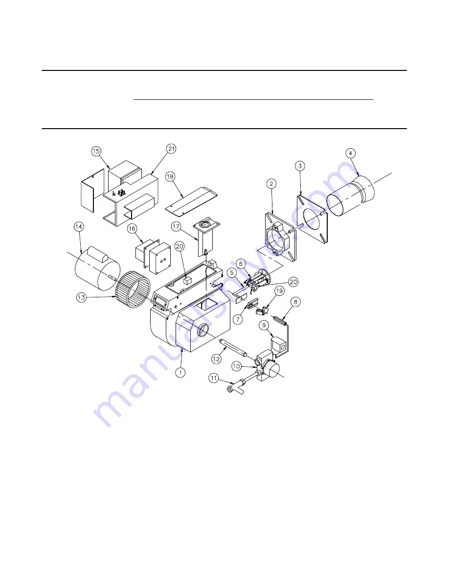
Typical Construction
Figure 22A-1
1.
Burner housing
12. Pump coupling
2.
Mounting flange
13. Fan wheel
3.
Flange gasket
14. Fan motor
4.
Blast tube
15. Flame safeguard
5.
Oil nozzle assembly
16. Ignition transformer
6.
Ignition electrodes
17. Damper assembly
7.
Housing plug
18. Housing cover
8.
Connecting pipe
19. Locating block
9.
Electric oil valve
20. Scanner or photocell
10.
Oil pump
21. Control enclosure
11.
Oil strainer


