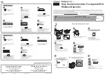
2. To wall-mount the unit, mount bracket (E) to the wall using 4 screws
(not 2. provided), as shown.
2
Connect the Cables
1. Plug one end of the CAT5 cable (A) into the RJ45 jack of the unit
(B).
2. Connect the free end of the CAT5 cable to the “Data and Power Out”
port 2. on the power injector.
3. To connect the unit through a hub or a switch to a PC, connect a
straight-3. through Ethernet cable between the network interface
card in the PC and the hub, and between the hub and the RJ45 “Data
In” port on the PoE adapter.
To connect the unit directly to a PC, connect a cross-over Ethernet cable
between the network interface card in the PC and the RJ45 “Data In”
port on the power injector.
3
Weatherproofing
After fully assembling and tightening the cables, use the provided self-
fusing, rubberbased tape strip and electrical tape (not provided; Proxim
recommends Scotch™ Super 33+ Vinyl Electrical Tape) to seal the
connection.
4 Power on the Unit
The power injector provides Power-over-Ethernet (PoE), supplying
electricity and wired connectivity to the unit over a single 24 AWG CAT5
(diameter .114 to .250 inches/2.9 to 6.4 mm). The unit is not 802.3af-
compatible. Always use the supplied power injector to ensure that the
unit is powered properly. Note that the Active Ethernet module provides
+48 VDC over a standard CAT5 Ethernet cable.
Once you have connected the power injector to the Ethernet cabling and
plugged the power injector cord into an AC outlet, the unit is powered on.
There is no ON/OFF switch on the unit. To remove power, unplug the AC
cord from the AC outlet or disconnect the RJ45 connector from the “Data
and Power Out” port on the power injector.
Depressing the Reload button (on the side of the power injector) for five
seconds during power-up remotely resets the radio to its factory default
settings. You will need to use the end of a pin or paperclip to depress the
button.
Note: To avoid damaging your router/switch, do not
connect the RJ45 port labeled “Data & Power Out”
from the power injector to your router/switch.
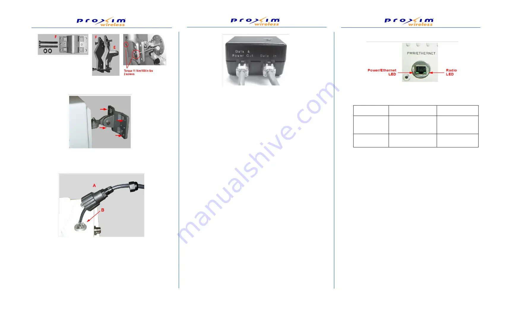
5 View LED
When the unit is powered on, it performs startup diagnostics. When
startup is complete, the LEDs show the unit’s operational state, as
follows:
6 Unit Initialization
Scan Tool Instructions
1. Power up, reboot, or reset the AP.1.
2. Double-click the ScanTool icon on the Windows desktop to launch
the 2. program. If the icon is not on your desktop, click
Start > All
Programs > ORiNOCO > AP-40000MR > ScanTool
.
ScanTool scans the subnet and displays all detected Access Points
Logging In
Once the AP has a valid IP Address and an Ethernet connection, you
may use your web browser to monitor and configure the AP. (To
configure and monitor using the command line interface, refer to the
AP-
4000MR User Guide
)
1. Open a Web browser on a network computer.
2. If necessary, disable the browser’s Internet proxy settings.
3. Enter the Access Point’s IP address in the browser’s 3. Address field
and press Enter or Go. This is either the dynamic IP address
assigned by a network DHCP server or the static IP address you
manually configured. See the Using ScanTool section above for
information on how to determine the unit’s IP address and manually
configure a new IP address, if necessary.
4. The login screen appears.
LED State
Power/Ethernet LED
Radio LED
Blinking Green
Power is on, unit is
booting up, Ethernet
link is down.
Radios are being
initialized.
Steady Green
Power is on, Ethernet
link is up.
Radios are being
operational.
4
3
2