D-Link DWL-3500AP, Configuration Manual
The D-Link DWL-3500AP is a high-performance wireless access point designed to provide seamless and reliable internet connectivity. Enhance your network by accessing its user manual, available for free download at manualshive.com. This comprehensive manual is packed with valuable instructions and troubleshooting tips to maximize the potential of your DWL-3500AP.
Share
Download


Reviews:
No comments
Related manuals for DWL-3500AP
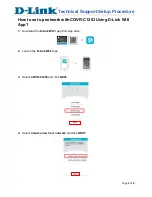
DIR-850L
Brand: D-Link Pages: 13

DWL-8600AP
Brand: D-Link Pages: 36

DWL-8600AP
Brand: D-Link Pages: 135
COVR-C1203
Brand: D-Link Pages: 6

PBE-5AC-400-ISO-EU
Brand: Ubiquiti Pages: 24

LP-1518
Brand: Lanpro Pages: 34

AD-2001
Brand: United Security Products Pages: 16

3CRWE91096A - Wireless LAN Building-to-Building...
Brand: 3Com Pages: 2

Wifi bridge
Brand: jbmedia Pages: 6

AW-NA830
Brand: AzureWave Pages: 47

TYLC4
Brand: TUYA Pages: 13

MAX-STREAM EA7250
Brand: Linksys Pages: 20

Board-C1
Brand: Canon Pages: 7

AIR-CAP3501E-A-K9
Brand: Cisco Pages: 34

AIR-AP1210 - Aironet 1200 - Wireless Access Point External
Brand: Cisco Pages: 35

Aironet 1520 Series
Brand: Cisco Pages: 66

1830 Series
Brand: Cisco Pages: 44

AIR-CAP1552H-x-K9
Brand: Cisco Pages: 24


