background image


edition: PROTEKT_EN-01 
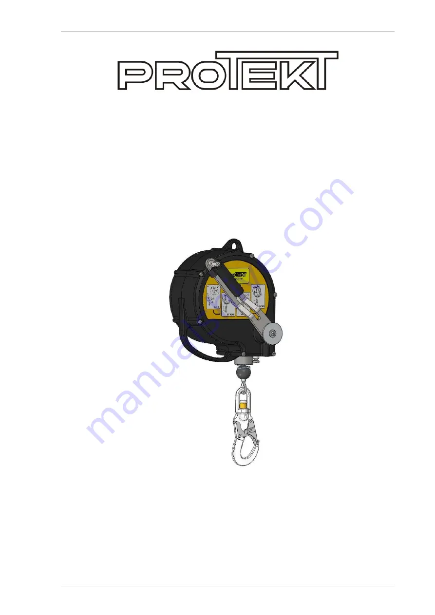


CRW 200 


RETRACTABLE TYPE FALL ARRESTER 

RESCUE LIFTING DEVICE 


SERVICE MANUAL 


CONTENTS 

1.  CRW 200 Technical specification

....................................... 


1.1. 

Description ............................................................... 


1.2. 

Technical data .......................................................... 


1.3. 

Standards ................................................................. 


1.4. 

Identification and marking ........................................ 

2.  Terms of servicing

 .............................................................. 

3.  Servicing equipment

 .......................................................... 

4.  Servicing operations

 .......................................................... 


4.1. The device dismantling .................................................. 


4.2. The retracting spring set maintenance and inspection .. 


4.3. The drum set maintenance and inspection .................... 


4.4 The brake set maintenance and inspection .................... 


4.5. The winch unit dismantling and maintenance ................ 


4.6. The device rebuilding .................................................... 

5.  Post assembly check

 ......................................................... 

6.  CRW200 - Spare parts

 ........................................................ 


10 
12 
13 

Summary of Contents for CRW 200

Page 1: ...tion and marking 2 Terms of servicing 3 Servicing equipment 4 Servicing operations 4 1 The device dismantling 4 2 The retracting spring set maintenance and inspection 4 3 The drum set maintenance and inspection 4 4 The brake set maintenance and inspection 4 5 The winch unit dismantling and maintenance 4 6 The device rebuilding 5 Post assembly check 6 CRW200 Spare parts 2 2 2 2 2 3 3 4 4 6 6 7 9 10...

Page 2: ...tic energy of the fall The rescue lifting device mode The device is equipped with hand operated winch with automatic brake which prevent against self contained descent of a person In the consequence of cranking the device cable is moved up and down under control 1 2 Technical data Max rated load 140kg Min rated load 50kg Working length 15m Dimensions acc to drawing in mm Weight 11kg Cable diam 4 8...

Page 3: ...ention For correct ordering servicing and maintenance personnel should be familiar with the specification of replacement parts All servicing and maintenance should be recorded in the device s IDENTITY CARD 3 SERVICING EQUIPMENT Common tools and some special equipment available from authorised service centres and the manufacturer are required for servicing and maintenance of CR 200 Manufacturer rec...

Page 4: ...nit to see if there are any cracks dents or chipped off pieces If any problems are detected the affected parts should be replaced 4 1 The device dismantling 4 1 1 Unscrew 6 screws 1 with the aid of Torx type wrench T 25 Open a cover 2 from cable drum side 4 1 2 Take off a clip size 38mm 3 from cable pilot sleeve 4 4 1 3 Pull out the cable sleeve 4 from casing opening 5 and move the cable out of th...

Page 5: ... screws 18 with the aid of Torx type wrench T 25 Open the cover set 19 Unscrew licking unit 20 and take off the washer 21 4 1 8 Unscrew 3 M8 bolts 22 with the aid of Allen wrench 6mm and take off the winch set 23 from the casing Take off the locking pin set 20 from the casing 4 1 9 Take off snap ring 20mm 24 and take off the brake unit 25 from the shaft Take off the snap ring 20mm 26 and washer 27...

Page 6: ...st the connector for correct operation If the connector is equipped with fall indicator check if it is not deformed Unwinding the cable from the drum inspect it against broken wires unbraided strands permanent deformations excessive corrosion Check the rope ferrules 3 against cracks or deformation Check if the rope s end 4 project outside the ferrule Replace the entire cable set in case of any dam...

Page 7: ...nit on the Rotating Jig Pay attention to lock the Jig s pin 1 in the part s relief 2 Secure the rotating jig table against rotation with the aid of pin 3 4 4 2 Take off the Φ8 locking ring 4 and the dog 5 from the dog s axle 6 Detach the dog s spring 7 from the pin 8 Carefully inspect dogs 5 attack edge cannot be worn down dog s axle 6 any axle movement is a failure the dog s springs 7 the spring ...

Page 8: ...f appropriate Don t clean or repair the friction ring If the ring is worn down or damaged it should be replaced with new one Assembly the components of the set in reverse order The M28 nut thread must be greased before screwing 4 4 5 Set up a torque spanner with the torque value of 60 Nm Tight the M28 nut 9 with the specified torque 4 4 6 Attach the dog s springs 17 to the pins 18 Mount the dogs 1...

Page 9: ...rrosion Metal parts may be cleaned with the aid of extraction naphtha or similar solvent Don t clean or repair the friction ring If the ring is worn down or damaged it should be replaced with new one Rebuild the winch unit in the following steps 4 5 4 Put on one friction ring 5 onto shaft Grease the shaft in pointed place 4 5 5 Put on the ratchet wheel 6 and friction ring 7 onto shaft 4 5 6 Grease...

Page 10: ...rews 9 Tight the locking pin set 7 screwing connection to winch set 8 4 6 4 Turning with the main shaft position the shaft s groove 9 opposite the retracting spring ending 10 so that inserting of the spring ending into groove is possible Put on the retracting spring cover set 11 on the base Pay attention to insert the ending 10 of the retracting spring into shaft s groove 9 and the hole 12 on the ...

Page 11: ...e screw with the aid of anaerobic adhesive 4 6 7 Mount the parallel key 26 into shaft slot and put the drum set 27 on the shaft Fix the drum set with the aid of M6 screw 28 and washer 29 4 6 8 Rotate the drum unit 8 full turns to the left in order to make initial tension of the retracting spring Insert the cable and the bumper s spring set 30 into casing slot Mount the Z38 locking ring 31 onto bus...

Page 12: ... the cable make sure that the cable retracts 5 2 Change over the device to EN1496 mode unlock the winch with the aid of the locking pin pull the crank plate lock the winch by loosening the locking pin 5 3 By turning the crank in both direction make sure that the cable is moved 6 4 Back to EN360 mode 5 5 4 Apply the next inspection sticker and mark relevant date in the next year 3 1 2 1 3 2 ...

Page 13: ...CRW 200 Service Manual 13 13 6 CRW 200 SPARE PARTS ...

Reviews: