background image


Notice  

The manufacturer will accept no responsibility for any electrical damage resulting from 

improper installation of the product, be that either damage to the vehicle itself or to the 
Unit. This Unit must be installed by a certified technician using all safety devices 

supplied. Please note that this guide has been written for properly trained Autostart 

technicians, a certain level of skill and knowledge is therefore assumed.  Please review 

the Installation Guide carefully before beginning any work. 

Warning 

This unit is designed for vehicles with an 

automatic 

Transmission only. 

Before installing the Unit, test that the vehicle will not start if the gear select lever is in the 
“Drive” position. If the vehicle starts in gear, install a manual-transmission Car Starter 
instead. 

DOC:


3.55


CA 

 – 

 September 9, 2004 

Manufactured in Canada by Autostart


A U T O M A T I C  

T R A N S M I S S I O N   R E M O T E   S T A R T E R  

S Y S T E M  


CT-5000 

Installation Guide 


Summary of Contents for CT-5000

Page 1: ...rtain level of skill and knowledge is therefore assumed Please review the Installation Guide carefully before beginning any work Warning This unit is designed for vehicles with an automatic Transmission only Before installing the Unit test that the vehicle will not start if the gear select lever is in the Drive position If the vehicle starts in gear install a manual transmission Car Starter instea...

Page 2: ...ia LED light 19 Installation Order 19 A basic introduction to the Relay 21 Troubleshooting Poor Transmitting Range 25 Trouble shooting Q A 25 Chirps 28 Diagnostics Parking Lights Flash Rate 29 Introduction This Guide contains all information pertinent to the installation Most if not all features are grouped in the User Guide and therefore should you need information on a feature you should refer t...

Page 3: ...nufacturer is not responsible for any radio or TV interference caused by unauthorized modifications to this equipment Such modifications could void the user s authority to operate the equipment Before You Get Started On vehicles with a manual Transmission always ensure that all Doors will get the Unit out of Ready Mode Switch the wire used so that it is triggered by all Doors Make sure that the Pa...

Page 4: ...tion When connecting the Module it is important to make sure the connector with the Ground wire is connected first before making the 12 volt connections Should the unit be powered before being grounded there could be serious damage to internal components of the unit Be careful not to power up a Module before it is properly grounded To avoid any accident it is a recommended to pull out the fuses fr...

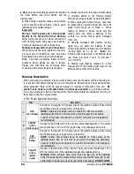
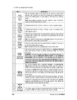
Page 5: ...and can cause erratic problems 2 PURPLE AC Tachometer input This wire tells the Module if the Engine is running or not It requires at least 1 8 volts AC and 1 5 Hz or faster at idle Common Tach references are the negative side of an injector the negative side of an Ignition Coil Camshaft sensor Crankshaft sensor or the Engine Control Module ECM NOTE A Tach signal that is too low will cause the Mod...

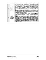
Page 6: ...Dome Light circuit Connect to a Dome Light wire testing 12 V with a Door open CAUTION You can only use a negative or a positive connection In other words only the NEGATIVE DOOR INPUT or the POSITIVE DOOR INPUT wire is connected It is essential that the Module be connected in such a way as to allow each one of the Doors to turn off Ready Mode the driver side Door Pin does not constitute by itself a...

Page 7: ...e connected to the Ground Out wire ensure that they are all diode isolated in order to avoid feedback and damaging the vehicle 11 GRAY Negative Door input This input should be used in vehicles that use a negative switching Dome Light circuit Connect to a Dome Light wire testing ground with a Door open CAUTION You can only use a negative or a positive connection In other words only the NEGATIVE DOO...

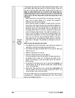
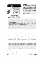
Page 8: ...between the negative Glow plug trigger on the relay and the negative Glow plug wire of the car This is to prevent feedback effects on the Glow plug indicator light on the instrument cluster the light on the dash would come on because of the feedback even though the circuit is off When the user remote starts the vehicle The Module will power up the Ignition circuit and wait to engage the Starter Mo...

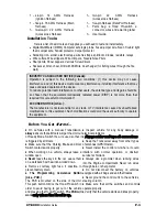
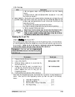
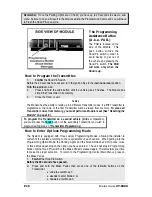
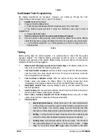
Page 9: ...is Flashing the Hood Pin It is a procedure that makes the Module go into the Programming Centre Once the Module is in the Programming Centre the Installer has no more than 20 seconds to get into one of the sub menus Failure to do so will result in the Module exiting the Programming Centre and the Installer will have to Flash the Hood Pin once more Remember You can use the Programming Assistance Bu...

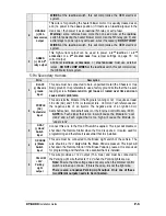
Page 10: ...rased from memory To erase all Transmitter codes from memory you must perform a Module reset See Resetting the Module on page 18 To program the Transmitter on a second vehicle Multi car Operation you must press the TRUNK button of the secondary Transmitter you wish to program during step 2 of Transmitter Programming How to Enter Options Programming Mode The System is equipped with three custom Pro...

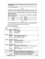
Page 11: ...on Controlled Door locks OPTION 1 Ignition Lock DISABLED OPTION 2 Ignition Lock ENABLED OPTION 3 Ignition UNLOCK ONLY OPTION 4 Ignition LOCK ONLY Function 2 Secure Lock OPTION 1 Secure Lock disabled 1 sec Disarm pulse OPTION 2 Secure Lock enabled in Smart Mode OPTION 3 Secure Lock disabled 0 5 Sec Disarm pulse OPTION 4 Secure Lock enabled in Normal Mode Function 3 Door Locks Pulse Timing OPTION 1 ...

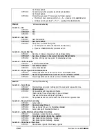
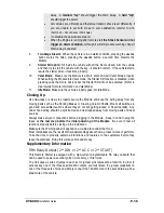
Page 12: ...d Function 5 Engine Type and Cold Weather Mode OPTION 1 Diesel Engine Mode and 20 minute run time in Cold Weather Mode OPTION 2 Gasoline Engine Mode and 4 minute run time in Cold Weather Mode OPTION 3 Diesel Engine Mode and 9 minute run time in Cold Weather Mode indicates default setting Mode 3 Function n 1 Sire Chirps OPTION 1 Warning Chirps only Lock Confirmation if the Lock button is press 2nd ...

Page 13: ... When the lower limit of 5 ms is reached the Horn Siren will sound for 1 4 second When the upper limit of 200 ms is reached the Horn Siren will sound for 3 4 second A system reset will set the system back to the default 30 ms Close the Hood to cancel the changes Auto Tach Programming Procedu Table 4 re NOTE If no tach has been programmed and the START STOP button is pressed there will be no start ...

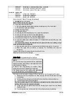
Page 14: ...n for Starter drag If the Starter cranks for too long carry out another Tach learning procedure 2 Test Hood Switch shutdown open the Hood the vehicle should shut down If it does not shut down check the Hood Pin switch and its connector 3 Test the Brake shutdown circuit With the vehicle running under the Remote Starter press and release the Brake Pedal The Engine should shut down immediately If the...

Page 15: ...le into Valet mode the Starter Kill function is disabled when pressing LOCK the Doors will lock but the Starter Kill will not be activated Refer to User Guide for more information on Valet Mode 11 Idle Mode Make sure the vehicle properly goes into Idle Mode Up wraps or screws to properly secure the Module a movi parts such as the Parking Brakes or Steering Column Shafts M good and acces under hood...

Page 16: ...controlled the through the OEM LOCK and UNLOCK wires Secure Lock saves the installer from connecting the ARM and DISARM wires and the LOCK and UNLOCK wires to the OEM LOCK and UNLOCK wires Upon receiving a remote start signal the system will unlock the Doors disarming the OEM Alarm 1 2 sec after the remote start the system will LOCK the Doors Please note most factory Alarm systems will not rearm w...

Page 17: ... open Pressing the UNLOCK button will unlock and disarm the vehicle and if no intrusion occurred the Siren will chirp twice if an intrusion occurred the Siren will chirp 4 times Option 3 Open Zone Notification if a Door is detected as open 10 sec after arming the Horn Siren will sound 3 times Also used for vehicles with Dome Light Delay Option 4 Chirps disabled the Siren will not chirp under any c...

Page 18: ...om memory and return all the Programming Options to the factory default values Resetting the Remote Car Starter is not a required process Most of the time you can avoid resetting by fixing the issue directly at the root of the cause 1 Flash the Hood Pin switch see Table 1 Once inside Programming Mode you have 10 seconds to complete the next step 2 Press and release the Break Pedal 6 times within 1...

Page 19: ...d during Events Playback 1 x Power up Reset Battery disconnected reconnected or dead 2 x Doors intrusion 3 x Shock Sense 4 x Hood 5 x Panic 6 x Ignition Installation Order The following is a suggested order for the Installation procedure It is intended as guide for novices to help make the process of installing a remote start module easier Time is wasted by rewiring the module when mistakes are ma...

Page 20: ...ires will not get squished We recommend using an aftermarket grommet when ever you drill a hole through the fire wall This will protect the wires from rubbing against the bare metal and possibly shorting out If you are installing an Alarm starter combo module mount the siren in the engine compartment at this time The next step is to pre wire the module This Is done on your work bench and not in th...

Page 21: ...arms Program the Remote control Program the Tach Signal Change the programming of the options if necessary Test the module s operations If all of the testing is successful the install is complete and the vehicle can be put back together A basic introduction to the Relay What is a relay A device that responds to a small current or voltage change by activating switches or other devices in an electri...

Page 22: ...etween 30 back from 87 to 87a Quenching Diodes It was said earlier that you energize a relay by applying positive from the battery to either 85 OR 86 and grounding the other terminal This is not absolutely true some relays are polarized if they have a quenching suppression diode A diode installed between the coil terminals 85 and 86 could be internal or external To activate the coil on this type o...

Page 23: ...ered during the remote starts The following example will be a Positive Park Light circuit that feeds back and activates the windshield wipers during remote starts Solution When power is applied to the OEM Park light wire it back feeds through the park light switch and activates the wipers Where the connection was made from the start modules Park light output and the vehicle s park light circuit th...

Page 24: ...he remote start module This becomes the negative trigger for the coil 86 Connects to the vehicle s Ignition wire This becomes the positive trigger for the coil 87 No connection This terminal is not used in this application The vehicle s OEM start wire is cut The side of the wire that is still connected to the Ignition switch becomes the Key Side of the starter wire The side of the wire that is sti...

Page 25: ...as well vans in general have an especially poor range The shape of the roof and A pillars brings about considerable radio frequency deflection in this case the signal from the remote control As a result the direction in which the vehicle is facing in relation to the remote control can affect the range Straight on standing in front of the vehicle generally gives you the greatest range the second be...

Page 26: ...ooked up correctly Has the clutch been bypassed properly for standard transmissions 6 The car starts but starter stays engaged Make sure ignition and crank are not common with the key out connected at rest May have to add relay i e Tercel Altima Did you make an Auto Tach Adjustment Weak Tach signal Bad ground 7 The car starts by remote but then the starter re engages Check ground wire Is Tach prog...

Page 27: ...but almost none when it is running Check for loose spark plug boot or faulty ignition wires cracked cap Try disconnecting blower motor 21 After about a half hour almost no range at all until the vehicle is started with the key again Does the vehicle have factory alarm keyless entry You might have to switch to a 433MHZ module Some GM Trucks Cavalier Sunfire Breeze Stratus Cirrus 22 Sometimes I have...

Page 28: ...under remote control Disarmed Notification 2 UNLOCK and disarm Transmitter Programmed Entering Mode 2 in Programming options 3 LOCK and arm while a zone is left unprotected Entering Mode 3 in Programming Options Door zone left unprotected 4 UNLOCK and disarm an intrusion was detected Entering Tach learning Mode 5 Siren or Horn Chirp Timing adjustment Constant up to 30 seconds Panic Mode causes the...

Page 29: ...pt to start the vehicle while the Module was in Valet Mode 2 pause 2 There was an attempt to start the vehicle while the Module was in Home Valet Mode ON solid Cold Weather Mode the Brake Pedal is being held down ON 2 sec The Hood is up and the Hood Switch line went to ground This is step one of the Programming Mode ON 3 sec First press of the START STOP button under Safe Start Entering Home Valet...

Reviews: