


PRONAR Sp. z o.o.
17-210 NAREW, UL. MICKIEWICZA 101A, WOJ. PODLASKIE
tel.:
+48 085 681 63 29
+48 085 681 64 29
+48 085 681 63 81
+48 085 681 63 82
fax:
+48 085 681 63 83
+48 085 682 71 10
www.pronar.pl
OPERATOR'S MANUAL
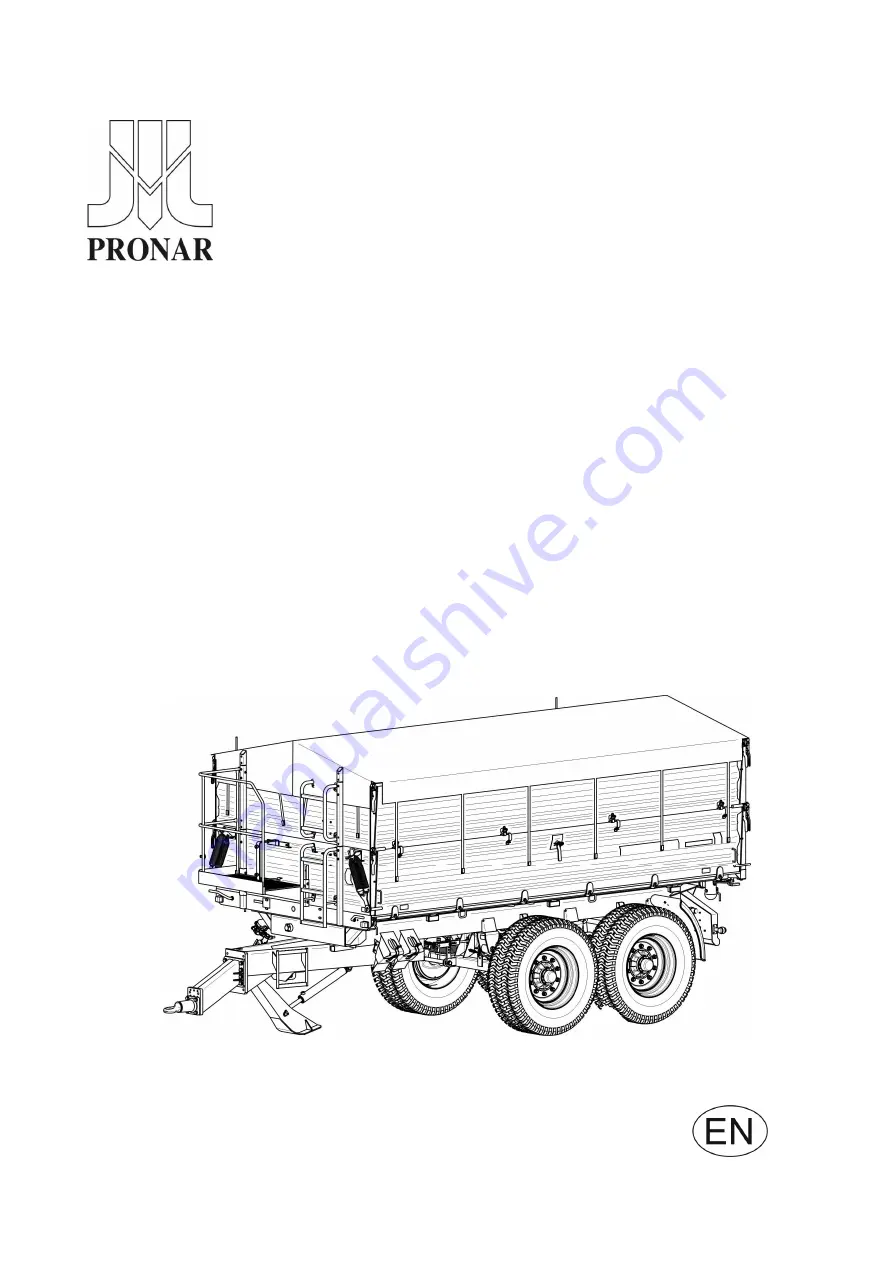
TRAILER
PRONAR T663/1
PRONAR T663/1 SILO
TRANSLATION OF THE ORIGINAL DOCUMENT
ISSUE 5D-01-2010
PUBLICATION NO. 45N-00000000-UM
Summary of Contents for T663/1
Page 2: ......
Page 6: ......
Page 11: ...SECTION 1 BASIC INFORMATION ...
Page 25: ...SECTION 2 SAFETY ADVICE ...
Page 44: ...Pronar T663 1 T663 1 SILO SECTION 2 2 20 ...
Page 45: ...SECTION 3 DESIGN AND OPERATION ...
Page 67: ...SECTION 4 CORRECT USE ...
Page 94: ...Pronar T663 1 T663 1 SILO SECTION 4 4 28 ...
Page 95: ...SECTION 5 MAINTENANCE ...
Page 121: ...SECTION 5 Pronar T663 1 T663 1 SILO 5 27 FIGURE 5 8 Trailer s lubrication points part 1 ...
Page 122: ...Pronar T663 1 T663 1 SILO SECTION 5 5 28 FIGURE 5 9 Trailer s lubrication points part 2 ...
Page 132: ...Pronar T663 1 T663 1 SILO SECTION 5 5 38 ...
Page 133: ...NOTES ...
Page 134: ... ...


