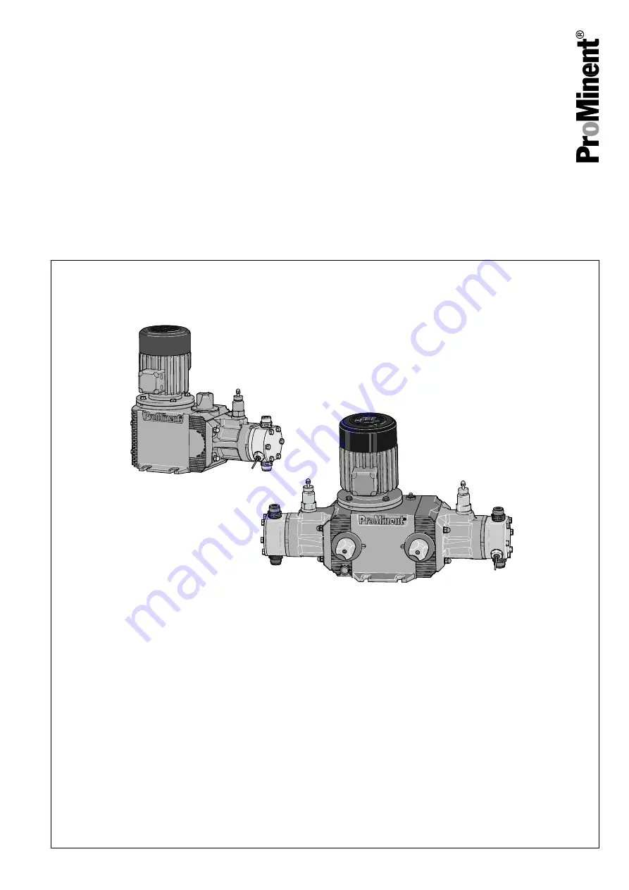
background image

Metering pumps

Hydro/ 2 and Hydro/ 3

Operating instructions

P_HY_0004_SW

EN

Original Operating Instructions (2006/42/EC)

984721

BA HY 017 10/15 EN

Please carefully read these operating instructions before use. · Do not discard.

The operator shall be liable for any damage caused by installation or operating errors.

The latest version of the operating instructions are available on our homepage.

ООО

 "

ПромХимТех

" - 

дистрибьютор


и


сервисный


партнер

 ProMinent

www.promhimtech.ru / [email protected]

Summary of Contents for Hydro 3 Series

Page 1: ...N Please carefully read these operating instructions before use Do not discard The operator shall be liable for any damage caused by installation or operating errors The latest version of the operating instructions are available on our homepage ООО ПромХимТех дистрибьютор и сервисный партнер ProMinent www promhimtech ru zakaz promhimtech ru ...

Page 2: ...o the precise designation of suppliers components in the Technical Data chapter for ease of finding the relevant information These operating instructions conform to current EU regulations applicable at the time of publication Please state identity code and serial number which you can find on the nameplate when you contact us or order spare parts This enables the unit type and material versions to ...

Page 3: ...commissioning 60 12 2 Disposal 61 13 Technical data 63 13 1 Performance data 63 13 2 Metering reproducibility 66 13 3 Viscosity 66 13 4 Weight 67 13 5 Wetted materials 67 13 6 Ambient conditions 67 13 6 1 Temperatures 67 13 6 2 Air humidity 69 13 7 Installation height 69 13 8 Housing degree of protection 69 13 9 Motor data 69 13 10 Diaphragm rupture sensor 71 13 11 Safety relief valve HP2 and HP3 ...

Page 4: ...poration for ATEX HP2 Machines 89 19 EC Declaration of Incorporation for ATEX HP3 Machines 90 20 EC Declaration of Conformity for ATEX HP2 Machines 91 21 EC Declaration of Conformity for ATEX HP3 Machines 92 22 Diagrams for setting the metering capacity 93 Table of contents 4 ...

Page 5: ...TFE Displacement body 0 Standard multi layer safety diaphragm with rupture signalling Dosing head design 0 no valve spring standard 1 With valve spring D Double ball valve only for SST and HCT H HV version for only for 025019 025060 Hydraulic connector 0 Standard threaded connector in line with technical data E With DIN ISO flange F With ANSI flange Design 0 with ProMinent logo standard 1 Without ...

Page 6: ... C With control motor 0 20 mA 115 V 60 Hz D With control motor 4 20 mA 115 V 60 Hz Hydraulic oil 0 Standard 1 Food approval for oil 2 Low temperature to 25 3 Low temperature Zone 2 Type power at 50 Hz Type Capacity Type Capacity Type Capacity bar l h bar l h bar l h 100003 1001 3 064007 641 7 025019 251 19 100006 1001 6 064015 641 15 025040 251 40 100007 1001 7 064018 641 18 025048 251 48 100009 1...

Page 7: ...i layer safety diaphragm with rupture signalling Dosing head design 0 no valve spring standard 1 With valve spring D Double ball valve for 100010 100035 064019 064060 and SST HTC H HV version for for 064019 064068 025048 025170 Hydraulic connector 0 Standard threaded connector in line with technical data E With DIN ISO flange F With ANSI flange Design 0 with ProMinent logo standard 1 Without ProMi...

Page 8: ... motor 0 20 mA 115 V 60 Hz D With control motor 4 20 mA 115 V 60 Hz Hydraulic oil 0 Standard 1 Food approval for oil 2 Low temperature to 25 3 Low temperature Zone 2 Type power at 50 Hz Type Capacity Type Capacity Type Capacity bar l h bar l h bar l h 100010 1001 10 064019 641 19 025048 251 48 100021 1001 21 064040 641 40 025100 251 100 100025 1001 25 064048 641 48 025120 251 120 100031 1001 31 06...

Page 9: ...ccordance with the European guidelines Ensure that the explosion group category and degree of protection specified on the label corresponds to or is better than the conditions prevalent in the intended field of application n The pump is only approved for use with flammable feed chemicals if it has the identity code option Multi layer safety diaphragm with visual rupture display is operated at back...

Page 10: ...mation contained in the operating instructions of the accessory devices at the different phases of their respective service lives Task Qualification Storage transport unpacking Instructed person Assembly Technical personnel service Planning the hydraulic installation Qualified personnel who have a thorough knowledge of metering pumps In areas at risk from explosion ATEX qualified person ATEX elec ...

Page 11: ...le dan gers based on their technical training and experience The electrical technician with an additional explosion protection qualifica tion is familiar with all the standards and regulations applicable to explo sion protection in particular but not however exclusively with all parts of EN 60079 electrical equipment for areas at risk of a gas explosion The electrical technician with an additional...

Page 12: ...plies specifically to intrinsically safe circuits The following information relates essentially to specifics in areas at risk from explosion and does not replace the standard operating instructions Only clean plastic parts carefully with a damp cloth to avoid electrostatic charges and sparks WARNING Warning of dangerous or unknown feed chemical Should a dangerous or unknown feed chemical be used I...

Page 13: ...he pump must only be opened at those points required to be opened by these operating instructions It may only be opened in other positions upon receipt of written authorisation from the ProMinent head office Heidel berg WARNING Adjusted pressure switches fail The switching point of the 42 V pressure switch must not be changed The ATEX pressure switch must not be reprogrammed It could result in ove...

Page 14: ...ed in their position Protective equipment May only be removed by Terminal box cover motor Electrical technician ATEX elec trical technician customer service Flange cover side Service only with ATEX version with add on power end Coupling flange inspection cover Service only with ATEX version without motor Motor connection inspec tion cover Service Protective cowling above the motor fan Service Only...

Page 15: ...laration of Conformity in the appendix are permitted in areas at risk from explosion PVDF is generally ruled out as material for the dosing head Only use PTFE as the material for the dosing head together with an elec trical diaphragm rupture sensor and a discharge side flow control Sound pressure level LpA 70 dB according to EN ISO 20361 at maximum stroke length maximum stroke rate maximum back pr...

Page 16: ...cape due to incorrect or improper storage or transportation The unit should only be stored or transported in a well packaged state preferably in its original packaging Only transport the unit with the locking screw not the bleed plug fitted to the oil filling opening The packaged unit should also only be stored or trans ported in accordance with the stipulated storage condi tions The packaged unit...

Page 17: ... refer to Technical Data chapter Ambient conditions Storage transport and unpacking 17 ...

Page 18: ... end C Liquid end 1 Stroke adjustment knob 2 Safety relief valve 3 Oil level indicator 4 Gear bleeding plug 5 Oil drain plug 6 Oil drain screw 7 Stroke sensor Option 8 Diaphragm rupture sensor P_HY_0006_SW 1 4 5 3 2 Fig 4 Liquid end 1 Discharge valve 2 Diaphragm mounting plate 3 Diaphragm rupture sensor 4 Suction valve 5 Liquid end Overview of device control elements 18 ...

Page 19: ... power end and the diaphragm if the liquid feed pressure becomes too high If the discharge side of the liquid end is blocked the safety relief valve 5 opens at a real opening pressure and allows the hydraulic oil to flow into the power end housing The real opening pressure lies above the nominal pressure the pressure stage see chap Technical Data This does not guarantee protection of the system ag...

Page 20: ...NG In an area at risk from explosion EX applies to selected equipment and methods With a dog clutch The claw on the motor shaft must be fixed at the correct height see Fig Ä Motor installation for versions without a motor on page 20 3 As you have converted an incomplete machine into a complete machine you must perform a conformity assessment risk assess ment create an EC Declaration of Conformity ...

Page 21: ...dro HP2 Size Motor flange Q 56C 2 06 52 32 80 200 50 71 B5 160 30 Dimensions in mm unless otherwise indicated Hydro HP3 Size Motor flange Q 56C 2 06 52 32 80 200 50 80 B 14 Ø 160 40 Dimensions in mm unless otherwise indicated The inner diameter of the shaft is 19 mm Assembly 21 ...

Page 22: ... opening and the walls The distance should be greater than 1 4 of the diameter of the air intake opening The fan must not suck in the exhaust air from other devices CAUTION Danger from incorrectly operated or inadequately maintained pumps Danger can arise from a poorly accessible pump due to incorrect operation and poor maintenance Ensure that the pump is accessible at all times Adhere to the main...

Page 23: ... cannot close correctly if they are not upright Ensure that the discharge valve is upright Capacity too low Vibrations can disrupt the liquid end valves Secure the metering pump so that no vibrations can occur 1 Take the dimensions m for the fastening holes from the appro priate dimensions or data sheets 2 Fix the pump base to the supporting floor with sufficient strong screws With externally moun...

Page 24: ...he event of continuous operation by the internal relief valve In the event of differing temperature classes amongst the diverse components operation of the complete pumps should be based on the component with the lowest temperature class Hydraulic diaphragm pumps are highly suitable although the design with Ex i diaphragm rupture sensor and a pressure side flow control is required Ensure that inst...

Page 25: ...r this purpose use a shut off valve a solenoid valve or a vacuum breaker CAUTION Suction problems possible The valves may no longer close properly with feed chemicals with a particle size of greater than 0 3 mm Install a suitable filter in the suction line CAUTION Warning of the discharge line rupturing With a closed discharge line e g from a clogged discharge line or by closing a valve the pressu...

Page 26: ...kness Only use clamp rings and hose nozzles that fit the respective hose diameter Always connect the lines without mechanical tension Only connect steel piping via a flexible piping section to a plastic valve body see the following figure 1 2 3 P_MOZ_0021_SW Fig 10 Connect the steel piping to the plastic pump body as shown 1 Steel piping 2 Flexible pipe section 3 Plastic valve body CAUTION Warning...

Page 27: ...ressure valve should be used to create a back pressure of approx 1 5 bar CAUTION Warning of unnoticed diaphragm rupture Only above approximately 2 bar system back pressure is a signal generated upon a diaphragm rupture Only rely on the diaphragm rupture sensor at back pres sures greater than 2 bar 7 1 1 Basic installation notes CAUTION Danger resulting from rupturing hydraulic components Hydraulic...

Page 28: ...OZ_0043_SW 2 1 A B PD 1 2 Fig 13 A standard installation B with pulsation damper 1 Main line 2 Storage tank Symbol Explanation Symbol Explanation Metering pump Foot valve with filter meshes Injection valve Level switch Multifunctional valve Manometer Legend for hydraulic diagram Installation 28 ...

Page 29: ...ed with a potential equalisation cable to each other cleanly and permanently to an electrically clean potential equalisa tion point e g with a potential equalisation bar on your system Note the enclosed documentation for the individual elec trical components Please note the relevant national regulations during installation WARNING Danger of electric shock Unprofessional installation may lead to el...

Page 30: ...n site prescribed in the area at risk from explosion WARNING ATEX pumps in areas at risk from explosion Use a suitable motor protection switch to protect power end motors Use motor protection approved for this application with Ex e motors Protection against warming caused by overloading Provide a time delay residual current device Ensure that motors are only installed and checked by a recognised c...

Page 31: ...r as shown in Ä Motor on page 30 Use an electrical isolating device in the mains supply cable such as a mains switch to be able to switch off the pump independently from the entire installation e g for repairs 1 Install a motor protection switch as the motors have no fuse 2 Install an emergency cut off switch or include the motor in the emer gency cut off management of the system 3 Only connect th...

Page 32: ...ING Risk of fire after a diaphragm rupture The electric diaphragm rupture sensor must switch off the pump immediately after a diaphragm rupture Connect the pump and the diaphragm rupture sensor to a control so that the pump is stopped immediately in the event of a diaphragm rupture CAUTION Danger resulting from unnoticed diaphragm rupture If the pump has been ordered with an electric diaphragm rup...

Page 33: ...phragm rupture Connect the stroke sensor to a suitable monitoring device according to the details in the chapter Technical Data also observe their technical data The monitor power supply installed by the customer must be able to evaluate the current variations of the Namur sensor for indicating a diaphragm rupture WARNING In the area at risk from explosion For the Namur sensor NJ1 5 8GM N also not...

Page 34: ...otential equalisation cable from the potential equalisation cables from this system cleanly and permanently to an electrically clean potential equalisation point e g to a potential equalisation bar on site Install the other units in line with their documentation Potential equalisation lines mandatory with ATEX Other units Installation 34 ...

Page 35: ... that feed chemical does not come into con tact with oxygen WARNING Hot surface In event the power end motor is loaded excessively its sur face may become very hot Avoid contact If necessary mount a guard plate WARNING Risk of burns with hot feed chemicals If hot feed chemicals can heat the liquid ends above the per missible surface temperatures persons can suffer burns from them Consider attachin...

Page 36: ...y equipment is connected in compli ance with the regulations CAUTION When using pumps with speed control observe the instruc tions in the frequency converter operating instructions CAUTION Danger of material damage Observe the details in the chapter Technical Data pres sure viscosity resistance CAUTION Feed chemical can escape unnoticed If the diaphragm rupture sensor does not stop the pump or no ...

Page 37: ...use of the safety relief valve The safety relief valve can only protect the motor and the gear only against illegal positive pressure that is monitored by the metering pump itself It cannot protect the system against positive pressure Protect the motor and gear of the system against posi tive pressure using other mechanisms Protect the system against illegal positive pressure using other mechanism...

Page 38: ...earthing dia grams in the appendix Check whether the potential equalisation lines are sitting correctly on the pump and connected to a clean potential equalisation point 8 1 Bleeding the liquid end When bleeding the liquid end or suction against pressure Relieve the suction and discharge line from pressure With dangerous or unknown feed chemicals take suitable protective measures according to the ...

Page 39: ... 1 and a brass bar 2 gently tap the PTFE ball seat above the valve ball see figure below Then with the valve in a damp condition allow it to prime 8 2 Calibrate the stroke control drive Option The stroke control drive is calibrated to the ordered dosing rate ex factory In event that you want the stroke control drive to be calibrated to another dosing rate please contact ProMinent Fig 15 Tapping th...

Page 40: ...ure that no elec trostatic charges are generated by excessive friction see warning label Replace wear parts such as bearings when there is an identifiable incidence of unacceptable wear The nom inal service life cannot be calculated with lubricated bearings Only use genuine spare parts as replacements A diagnostic device for bearing damage is very useful for the premature detection of bearing dama...

Page 41: ...measures before working on the pump e g safety glasses safety gloves Observe the safety data sheet for the feed chemical Drain and flush the liquid end before working on the pump WARNING Danger of an electric shock When working on the motor or electrical auxiliary equipment there is a danger of an electric shock Before working on the motor take note of the safety instructions in its operating inst...

Page 42: ...Abnormal temperatures n Abnormal odours n Abnormal vibrations n Other peculiarities WARNING In areas at risk from explosion stop the pump immediately and rectify these peculiarities ProMinent Services may be needed if required Maintenance 42 ...

Page 43: ...re signaller Technical personnel Check the secure seating of the pressure limitation valve 50 Nm Technical personnel With the pump running check whether bubbles rise in the window of the bleed valve Technical personnel Check that the flow is correct Allow the pump to prime briefly Technical personnel Check the tightness of the entire liquid end particularly around the leakage hole Technical person...

Page 44: ...s WARNING Risk of burns due to hot hydraulic oil The hydraulic oil may become very hot when the pump is exposed to extensive loading When draining oil avoid contact with the oil running out WARNING If the pump must be operated using hydraulic oil compatible with foodstuffs then only foodsafe hydraulic oil must be used Drain the hydraulic oil For the double head versions perform the following work ...

Page 45: ...window 6 is covered Type Level of covering HP2 1 3 HP3 1 3 3 Start the pump 4 Allow the pump to run for a further 1 2 minutes 5 Top up with hydraulic oil if necessary 6 Screw the gearbox vent stopper 3 back in Do not close the bleed valve 7 Close the safety relief valve 1 loosen the knurled screw 8 Check whether these whole openings are tightly sealed again especially in the area at risk from expl...

Page 46: ...fications in the Storage Transport and Unpacking chapter prior to shipping the pump CAUTION Warning of feed chemical spraying around Feed chemical can spray out of the hydraulic components if they are manipulated or opened due to pressure in the liquid end and adjacent parts of the system Disconnect the pump from the mains power supply and ensure that it cannot be switched on again by unauthor ise...

Page 47: ... pumps Only use new components that are especially adapted to fit your valve both in terms of shape and chemical resistance Use the correct spare parts kits If in doubt refer to the exploded drawings and ordering information on our web site www prominent com or if included the Supple mentary CD for Operating Instructions Unsuitable spare parts for the valves may lead to problems for the pumps Only...

Page 48: ...take note of the sequence Teflon Metal Teflon Metal 1 Slide into the valve body 1 one after another n one seal 2 and one valve seat 3 correct n one seal 2 and one valve bushing 4 n If fitted allow one spring to slide into the spring guide of the valve seat 3 n slide one ball 5 into the valve body 1 n one seal 2 and the second valve seat 3 correct n one seal 2 and the second valve bushing 4 n If fi...

Page 49: ...ling No impurities must contact the multi layer diaphragm Do not inspect the insert disc For the double head versions and add on power ends perform the fol lowing work simultaneously on both dosing heads Position numbers see chapter Maintenance 1 Turn the stroke adjustment dial 2 more than 100 to the stop 2 Unscrew the gearbox vent stopper 3 3 Place an oil trough under the hydraulic end 4 Unscrew ...

Page 50: ...on from the diaphragm mounting plate 2 9 Place the new diaphragm diaphragm anchor combination into the diaphragm mounting plate 2 10 Push the diaphragm spring 3 with the spring collar 5 on to the diaphragm anchor 6 11 Secure the spring collar 5 using the safety collar 4 12 Replace the O ring 7 between the diaphragm mounting plate 2 and the hydraulic end 13 Place the diaphragm 1 with the diaphragm ...

Page 51: ...es 5 Screw the gearbox vent stopper 3 back in Do not close the bleed valve 6 Close the safety relief valve 1 loosen the knurled screw 7 Check the pump for tightness by using maximum back pressure Check the tightening torque of the dosing head screws again after 24 hours of operation 10 3 Repair the diaphragm rupture sensor WARNING Warning of feed chemical After diaphragm rupture additional feed ch...

Page 52: ...ensor from the power supply 2 When changing the diaphragm unscrew the diaphragm rupture sensor from the dosing head 3 Grasp the upper section 2 of the diaphragm rupture sensor 4 Hold the body 5 in place with an open ended spanner 5 Unscrew the top of the diaphragm rupture sensor 6 Clean the soiled parts 7 Lay the new separating diaphragm 3 with the light side PTFE down into the upper section 2 8 L...

Page 53: ...f the diaphragm rupture sensor 6 Clean any dirty parts 7 Lay the new separating diaphragm 3 with the light side PTFE down into the top part 2 8 Place the disc 4 in the top part 2 9 Place the spring into the body 5 10 Move the body 5 close to the top part 2 ð The spring 6 should sit correctly on the spring seat 3a 11 Screw the body 5 into the top part and tighten 12 Connect the diaphragm rupture se...

Page 54: ...ssembly for calibration Materials required n Measuring beaker n Stop watch 1 Switch off the pump 2 Turn the stroke adjustment dial to maximum beyond 100 to the stop 3 API versions only Remove the metal cap from the stroke adjust ment dial 4 Remove the cover 4 from the stroke adjustment dial and slacken off the screw 3 beneath slightly 5 Guide the suction line into a measuring beaker see Fig 22 6 F...

Page 55: ...y until the 100 marking is precisely above the indicating slot 2 14 Carefully tighten the screw 3 in the stroke adjustment dial and replace the cap 4 15 API versions only Press the metal cap on to the stroke adjustment dial Repairs 55 ...

Page 56: ...e only performed by experienced personnel with the requisite knowl edge Make sure that a recognised competent person checks the electrical installation and in particular the intrinsically safe electric circuits WARNING ATEX pump in area at risk from explosion Static electricity can cause ignition sparks Always earth the discharge and suction lines first before working on the pump WARNING Fire haza...

Page 57: ...c shock On conducting parts of the motor with an integrated fre quency converter and on the lines themselves there remains a risk of an electric shock for 3 minutes after switching off the mains voltage After switching off allow the device to stand for 3 minutes before opening the terminal box CAUTION Only motors with a frequency converter The motor can be damaged If a motor with an integrated fre...

Page 58: ...hydraulic oil in the power end Refill with hydraulic oil until oil inspection window is 1 3 covered see Diaphragm change in the chapter Repair Investigate and clear the cause of the oil loss Instructed per sonnel The oil inspection window is leaking Replace the oil inspection window as per the operating instructions Technical per sonnel Indicating dial is set incorrectly Set indicating dial see Ca...

Page 59: ...separating diaphragm of the diaphragm rupture sensor see Replacing the separating diaphragm diaphragm rupture sensor in the chapter Repair Technical per sonnel The power end motor is very hot The discharge line is seriously constricted n Rectify any constriction of the dis charge line n Have the safety relief valve checked Technical per sonnel All other faults Other causes Call the ProMinent Servi...

Page 60: ... liquid end and on the housing after operation This chemical residue could be hazardous to people It is mandatory that the safety note relating to the Storage Transport and Unpacking chapter is read before shipping or transporting the unit Thoroughly clean the liquid end and the housing of chemicals and dirt Adhere to the safety data sheet for the feed chemical WARNING Warning of dangerous or unkn...

Page 61: ...nect the pump from the mains power supply 2 Depressurise and bleed the hydraulic system around the pump 3 Flush the liquid end with a suitable medium Observe the safety data sheet Flush the dosing head thoroughly when using haz ardous feed chemicals 4 Drain the hydraulic oil see chapter Maintenance 5 Thoroughly clean the liquid end and the housing of chemicals and dirt 6 Possible additional work s...

Page 62: ...d due to hydraulic oil The pump contains hydraulic oil which can cause damage to the environment Drain the hydraulic oil from the pump Note the local guidelines currently applicable in your country Decommissioning and Disposal 62 ...

Page 63: ... 2 0 187 3 5 G 3 4 10 064025 64 25 2 0 212 3 5 G 3 4 10 025019 25 19 5 3 60 3 5 G 3 4 10 025040 25 40 5 3 125 3 5 G 3 4 10 025048 25 48 5 3 150 3 5 G 3 4 10 025060 25 60 5 3 187 3 5 G 3 4 10 025068 25 68 5 3 212 3 5 G 3 4 10 Material version SST HCT with double ball valve Alternative double ball valve SST with RP 3 8 HV design G1 DN 15 Maximum back pressure for liquid ends in material version PVT ...

Page 64: ...0 025040 25 362 48 12 7 150 3 5 G 3 4 10 025048 25 362 58 15 3 180 3 5 G 3 4 10 025060 25 362 72 19 0 224 3 5 G 3 4 10 Material version SST HCT with double ball valve Alternative double ball valve SST with RP 3 8 HV design G1 DN 15 Maximum back pressure for liquid ends in material version PVT 25 bar The metering capacity can deviate from the details above with the HV ver sion All figures refer to ...

Page 65: ... 25 100 13 4 125 3 5 G 1 10 025120 25 120 13 4 150 3 5 G 1 10 025150 25 150 13 4 187 3 5 G 1 10 025170 25 170 13 4 212 3 5 G 1 10 Material version SST HCT with double ball valve Alternative double ball valve SST with RP 3 8 HV design 1 1 4 DN 20 HV version G 1 DN 15 Maximum back pressure for liquid ends in material version PVT 25 bar The metering capacity can deviate from the details above with th...

Page 66: ...e Alternative double ball valve SST with RP 3 8 HV design 1 1 4 DN 20 HV version G 1 DN 15 Maximum back pressure for liquid ends in material version PVT 25 bar The metering capacity can deviate from the details above with the HV ver sion All figures refer to water at 20 C Priming lift priming pressure dry determined for empty suction line and empty liquid end and as well as clean and moistened val...

Page 67: ... head 48 13 5 Wetted materials Material version Liquid end Suction pressure connector Seals Ball seat Valve balls SST Stainless steel 1 4571 1 4404 1 4404 Stainless steel 1 4581 PTFE ZrO2 Ceramic PVT PVDF PVDF PTFE PTFE Ceramic HCT Hastelloy C Hastelloy C PTFE Hastelloy C Ceramic 13 6 Ambient conditions 13 6 1 Temperatures Data Value Unit Storage and transport temperature 10 50 C Ambient temperatu...

Page 68: ...ng pressure 90 C Minimum temperature Standard 10 C Minimum temperature Low temperature Zone 2 20 C Data Value Unit Max temperature long term at max oper ating pressure 90 C Max temperature for 15 min at max 2 bar 120 C Minimum temperature Standard 10 C Minimum temperature Low temperature Zone 2 20 C Minimum temperature Low temperature 25 C Data Value Unit Max temperature long term at max oper atin...

Page 69: ...gently advise that you contact a specialist for ATEX motors when using ATEX pumps 13 8 Housing degree of protection Data Value Protection against contact and humidity IP 55 according to DIN VDE 470 EN IEC 60529 13 9 Motor data HP2 and HP3 Identity code specification Phase protection Rated voltage Mains supply fre quency Rated output HP2a Remarks S 3 phase IP 55 220 240 V 380 420 V 50 Hz 0 37 kW 25...

Page 70: ...0 V 380 420 V 50 Hz 0 75 kW with PTC speed control range 1 5 P1 3 ph II2GEEXeIIT3 250 280 V 440 480 V 60 Hz 0 75 kW P2 3 ph II2GEEX dIICT4 250 280 V 440 480 V 60 Hz 0 75 kW with PTC speed control range 1 5 R Z 3 phase IP 55 230 V 400 V 50 60 Hz 0 75 kW with PTC speed control range 1 20 with external fan 1 ph 230 V 50 60 Hz V0 1 ph AC IP 55 230 V 10 50 60 Hz 0 75 kW Variable speed motor with inte g...

Page 71: ...nsor according to the chapter Installation elec trical Observe its documentation Sensor name NJ1 5 8GM N 5 25 V DC in accordance with Namur or DIN 19234 potential free design Data Value Unit Rated voltage 8 VDC Power consumption active surface uncovered 3 mA Power consumption active surface cov ered 1 mA Rated switching distance 1 5 mm Ri 1 kΩ Cable colour Polarity blue brown Install the sensor ac...

Page 72: ...Installation elec trical 5 25 V DC in accordance with Namur or DIN 19234 potential free design Data Value Unit Rated voltage 8 VDC Power consumption active surface uncovered 3 mA Power consumption active surface cov ered 1 mA Rated switching distance 1 5 mm Ri 1 kΩ Cable colour Polarity blue brown Install the sensor according to the chapter Installation elec trical Observe its documentation The se...

Page 73: ... Sound pressure level HP2a Hp3a Sound pressure level LpA 70 dB according to EN ISO 20361 at maximum stroke length maximum stroke rate maximum back pressure water 13 17 Supplement for modified versions With Identcode specification Version M modified Technical data of pumps in the modified version can deviate from those of the standard pumps They can be queried by stating the details of the serial n...

Page 74: ...essure connection assy 4 Suction connection assy 5 Diaphragm Reinforce plate only with PVT 14 2 Spare parts kits The spare part kits include the replacement parts for the liquid ends Standard delivery for material version PVT 1 Diaphragm 1 Suction connection assy 1 Pressure connection assy 2 Valve balls 1 Set of seals compl Standard delivery for material version SST HCT 1 Diaphragm 2 Valve balls 1...

Page 75: ...r double ball valves 1005555 HCT 1009573 SST with valves fully assembled 1005554 for types 100035 100031 100025 100021 100010 064068 064060 064048 064040 064019 for liquid end Material version Order no FMH 60 DN 10 PVT 1005552 SST 1005553 SST for double ball valves 1005555 HCT 1009573 SST with valves fully assembled 1005554 for types 025170 025150 025120 025100 025048 for liquid end Material versi...

Page 76: ...100 025048 1005547 for liquid end Pump type Order no FMH 60 064068 064060 064048 064040 064019 100035 100031 100025 100021 100010 1006482 FMH 150 025170 025150 025120 025100 025048 1006483 14 4 General The pump uses an hydraulic oil that lubricates the gear at the same time Use Manufacturer Name Viscosity class Part no Standard Mobil Mobilube 1 SHC 75W 90 1005823 or comparable hydraulic oil Use Ma...

Page 77: ...plied amount of oil Type Single head design Double head version HP 2 approx 2 5 l approx 2 9 l 3 0 l HP 3 approx 3 5 l approx 4 0 l 4 0 l Spare part Order no Seal for the oil drainage stopper 1004803 Seal Ordering Information 77 ...

Page 78: ...iagram is not binding Liquid end A B C D E F G HM 25 SST HCT 152 239 7 50 DN10G3 4A 108x42 414 HM 60 SST HCT 165 240 0 5 51 DN10G3 4A 108x57 415 HM 60 SST HV 165 243 5 0 5 57 DN15G1A 108x57 421 HM 25 for types 064007 064015 064018 064022 064025 100003 100006 100007 100009 100010 HM 60 for types 025019 025040 025048 025060 025068 Hydro HP2 HP2a H dimensions sheet Dimensional Drawings 78 ...

Page 79: ...195 242 20 5 55 DN10Rp3 8 419 Standard motor Motor controllable EExe motor EExde motor Motor with fre quency converter L 377 413 469 438 569 F 214 244 81 110 12 215 B 406 G D E L A C 61_02 101_00_02 73 P_HY_0020_SW Fig 25 Diagram is not binding Liquid end A B C D E F G HM 60 SST HCT 165 240 12 5 51 DN10G3 4A 108x57 457 HM 150 SST HCT 191 247 0 5 65 DN15G1A 128x76 471 HM 60 for types 064019 064040 ...

Page 80: ... DN10Rp3 8 461 Standard motor Motor controllable EExe motor EExde motor Motor with fre quency converter L 456 553 459 499 626 F 190 220 12 83 84 206 B 496 G H D E L A C 61_02 101_00_03 73 P_HY_0021_SW 16 7 Fig 26 Diagram is not binding Liquid end A B C D E F G H HM 25 SST HCT 152 239 7 50 DN10G3 4A 108x42 596 562 HM 60 SST HCT 165 240 0 5 51 DN10G3 4A 108x57 598 564 HM 60 SST HV 165 243 5 0 5 57 D...

Page 81: ...EExe motor EExde motor Motor with fre quency converter L 377 413 369 438 569 F 214 244 12 95 110 215 B 540 G H D E L A C 61_02 101_00_04 73 P_HY_0022_SW 16 7 Fig 27 Diagram is not binding Liquid end A B C D E F G H HM 60 SST HCT 165 240 12 5 51 DN10G3 4A 108x57 641 590 HM 150 SST HCT 191 247 0 5 65 DN15G1A 128x76 670 604 HM 60 SST HV 165 243 5 12 5 57 DN15G1A 108x57 653 597 HM 150 SST HV 203 251 6...

Page 82: ...r controllable EExe motor EExde motor Motor with fre quency converter L 456 553 459 499 626 F 449 485 18 12 18 314 350 63 B 395 G D E L 133 A C 61_02 101_00_09 74 P_HY_0023_SW Fig 28 Diagram is not binding Liquid end A B C D E F G HM 25 SST HCT 152 95 59 50 DN10G3 4A 108x42 444 HM 60 SST HCT 165 96 52 51 DN10G3 4A 108x57 445 HM 60 SST HV 165 99 49 57 DN15G1A 108x57 451 HM 25 for types 064007 06401...

Page 83: ... DN10Rp3 8 449 Standard motor Motor controllable EExe motor EExde motor Motor with fre quency converter L 427 463 419 488 619 61_02 101_00_13 74 P_HY_0024_SW Fig 29 Diagram is not binding Liquid end A B C D E F G HM 60 SST HCT 165 96 64 51 DN10G3 4A 108x57 495 HM 150 SST HCT 191 104 50 65 DN15G1A 128x76 506 HM 60 SST HV 165 100 61 57 DN15G1A 108x57 501 HM 60 for types 064019 064040 064048 064060 0...

Page 84: ...499 Standard motor Motor controllable EExe motor EExde motor Motor with fre quency converter L 506 603 509 549 676 61_02 101_00_10 74 P_HY_0025_SW Fig 30 Diagram is not binding Liquid end A B C D E F G H HM 25 SST HCT 152 92 59 50 DN10G3 4A 108x42 596 562 HM 60 SST HCT 165 93 52 51 DN10G3 4A 108x57 598 564 HM 60 SST HV 165 97 49 57 DN15G1A 108x57 610 571 HM 25 for types 064007 064015 064018 064022...

Page 85: ... controllable EExe motor EExde motor Motor with fre quency converter L 427 463 419 488 619 61_02 101_00_14 74 P_HY_0026_SW Fig 31 Diagram is not binding Liquid end A B C D E F G H HM 60 SST HCT 165 93 64 51 DN10G3 4A 108x57 641 590 HM 150 SST HCT 191 101 50 65 DN15G1A 128x76 670 604 HM 60 SST HV 165 97 61 57 DN15G1A 108x57 653 597 HM 150 SST HV 203 105 40 75 DN20G1 1 4A 128x76 690 612 HM 60 for ty...

Page 86: ...4040 064048 064060 064068 100010 100021 100025 100031 100035 HM 150 for types 025048 025100 025120 025150 025170 Dimension with double ball valve Liquid end A B C D E G H HM 60 SST HCT 195 95 43 55 DN10Rp3 8 650 594 Standard motor Motor controllable EExe motor EExde motor Motor with fre quency converter L 506 603 509 549 676 Dimensional Drawings 86 ...

Page 87: ...16 Earthing drawing 6 2 3 P_HY_0044_SW 2 Motor 3 Heating cartridge option 6 Actuator Simplex single head Hydro HP2 and HP3 with actuator and heating cartridge Earthing drawing 87 ...

Page 88: ...event of a modification to the product not agreed with us Extract from the EC Declaration of Conformity Designation of the product Metering pump product range Hydro 2 Hydro 3 and Hydro 4 Product type HP2a HP3a HP4a Serial number See nameplate on the unit Relevant EC directives EC Machinery Directive 2006 42 EC EC EMC Directive 2004 108 EC Compliance with the protection targets of the Low Voltage D...

Page 89: ... or 3 Serial number see nameplate on the device Relevant EC directives EC ATEX Directive 94 9 EC EC Machinery Directive 2006 42 EC EC EMC Directive 2004 108 EC Compliance with the protection targets of the Low Voltage Directive 2006 95 EC according to Appendix I No 1 5 1 of the Machinery Directive 2006 42 EC Harmonised standards applied in particular EN 13463 1 2009 EN 13463 5 2011 EN ISO 12100 20...

Page 90: ...tive 94 9 EC Product type HP3a A 0 with the characteristic 1 or 3 or 4 0 or 1 or 3 Serial number see nameplate on the device Relevant EC directives EC ATEX Directive 94 9 EC EC Machinery Directive 2006 42 EC EC EMC Directive 2004 108 EC Compliance with the protection targets of the Low Voltage Directive 2006 95 EC according to Appendix I No 1 5 1 of the Machinery Directive 2006 42 EC Harmonised st...

Page 91: ...cordance with the ATEX Direc tive 94 9 EC Product type HP2a 0 with characteristics L or P and 1 or 2 or V and 2 0 or 1 or 3 Serial number see nameplate on the device Relevant EC directives EC ATEX Directive 94 9 EC EC Machinery Directive 2006 42 EC EC EMC Directive 2004 108 EC Compliance with the protection targets of the Low Voltage Directive 2006 95 EC according to Appendix I No 1 5 1 of the Mac...

Page 92: ...cordance with the ATEX Direc tive 94 9 EC Product type HP3a 0 with characteristics L or P and 1 or 2 or V and 2 0 or 1 or 3 Serial number see nameplate on the device Relevant EC directives EC ATEX Directive 94 9 EC EC Machinery Directive 2006 42 EC EC EMC Directive 2004 108 EC Compliance with the protection targets of the Low Voltage Directive 2006 95 EC according to Appendix I No 1 5 1 of the Mac...

Page 93: ... 064015 064007 0 5 10 15 20 25 0 20 40 60 80 100 064025 0 64 32 30 20 10 0 064022 064025 064018 064015 064007 0 15 30 45 60 75 0 20 40 60 80 100 025060 025048 025040 025019 025068 025060 025068 025048 025040 025019 0 20 10 20 30 60 80 40 0 Fig 32 Metering capacity C at medium back pressure according to the stroke length s and metering capacity C on the basis of back pressure p for different types ...

Page 94: ... 100 025150 025170 025120 025100 025048 025150 025170 025120 025100 025048 0 20 10 160 180 0 30 80 120 0 50 60 0 100 10 20 30 50 40 100031 100035 100025 100021 100010 s s s C l h C l h C l h C l h C l h C l h p bar p bar p bar Fig 33 Metering capacity C at medium back pressure according to the stroke length s and metering capacity C on the basis of back pressure p for different types of a series D...

Page 95: ...95 ...

Page 96: ... Schuhmachergewann 5 11 69123 Heidelberg Germany Telephone 49 6221 842 0 Fax 49 6221 842 419 Email info prominent com Internet www prominent com ООО ПромХимТех дистрибьютор и сервисный партнер ProMinent www promhimtech ru zakaz promhimtech ru ...

Reviews: