background image

PRODUCT MANUAL FOR WALL MOUNT SERIES ASSEMBLIES

                                         Page 1 of 15 

[email protected]


PRODUCT MANUAL FOR WALL MOUNT SERIES ASSEMBLIES 


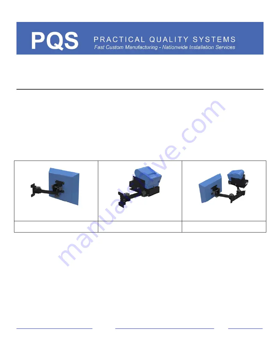
Wall Mount w/ 8” arm and a screen pan and tilt head 


PN 80000   

Wall Mount w/ 8” arm and a 

Universal Printer Mounting Tray


PN 80002  

Dual Wall Mount w/ 2- 8” arms, a screen pan and tilt head, and a    

PN 80003 

Universal Printer Mounting Tray


80000 80002 80003 


WW.PRACTICALQUALITYSYSTEMS.COM           (818) 993-1022


          Document Number:10010901-UM


Summary of Contents for 80000

Page 1: ...ES ASSEMBLIES Wall Mount w 8 arm and a screen pan and tilt head PN 80000 Wall Mount w 8 arm and a Universal Printer Mounting Tray PN 80002 Dual Wall Mount w 2 8 arms a screen pan and tilt head and a PN 80003 Universal Printer Mounting Tray 80000 80002 80003 WW PRACTICALQUALITYSYSTEMS COM 818 993 1022 Document Number 10010901 UM ...

Page 2: ...s 6 4 2 Attaching the VESA pan and tilt head to a VESA standard flat panel monitor touch screen or terminal 6 4 3 Basic steps for installing a Universal Printer Mounting Tray UPMT 6 5 1 Attaching a pan and tilt head or Universal Printer Mounting Tray to the end of the arm 6 5 2 Adjusting the side to side position of a pan and tilt head or Universal Printer Mounting Tray UPMT 7 5 3 Adjusting the up...

Page 3: ...________ Figure 1 P1 and P3 mounting plates and positions 10 Figure 2 A P1 mounting plate with one 8 arm 10 Figure 3 P3 mounting plate with two 8 arms 11 Figure 4 One 8 arm and a VESA pan and tilt head 12 Figure 5 Wall Mount w 8 arm and a Universal Printer Mounting Tray PN 80002 13 Figure 6 Wall Mount w 8 arm and a screen pan and tilt head PN 80000 14 Figure 7 Dual Wall Mount w 2 8 arms a screen p...

Page 4: ...th the mounting plate against the mounting surface to determine its best location 3 Pivot the arm so that they can be rotated through their entire range of motion and does not conflict with the surrounding surfaces Be sure to take into consideration the additional space that the equipment will need once it is attached to the end of the arm 4 Once the mounting location has been determined mark the ...

Page 5: ... Philips securing screws are not used To remove the arm from the SB bracket unscrew and remove the five point knob from the top of the SB bracket and slide the arm out 2 Remove the pan and tilt from the arm s 3 Remove the arm s with the SB bracket s from the mounting plate 4 Remove the arm s from the SB bracket s 5 Securely attach the mounting plate to the mounting surface with four or more fasten...

Page 6: ...s in the VESA pan and tilt head with the pattern of four threaded holes on the back of the screen 3 Loosely install the four screws through the VESA pan and tilt head and into the threaded holes on the back of the screen Do not fully tighten the screws until all of the screws are threaded into the back of the screen 4 3 Basic steps for installing a Universal Printer Mounting Tray UPMT 1 Remove the...

Page 7: ...ing knob securely 5 3 Adjusting the up and down position of the pan and tilt head 1 Carefully and firmly grasp the monitor at the top center of the screen to support its entire weight 2 Slightly loosen both of the four point knobs on both sides of the pan and tilt head just enough so that the monitor can be moved up and down slightly 3 While still firmly holding the monitor slowly raise or lower i...

Page 8: ...ition of the arm If your application requires additional security to hold the desired arm position it can be more securely locked by slightly tightening the SB locking screw If you have removed the SB brackets to install the mounting plate on top of a flat horizontal surface this locking feature is not available PLEASE NOTE if the factory setting of the locking screw is changed it must be reset to...

Page 9: ...indicate that they are low on printing paper when they are tilted too far forward 9 2 UPMT cabling tips Route the data and power cables and connect them loosely to the printer After testing your printer for correct operation use small plastic cable ties or hook and loop ties to attach the cables to the metal tie loops at the rear of the UPMT be sure that the cable connectors will not be strained w...

Page 10: ... SERIES ASSEMBLIES Page 10 of 15 info practicalqualitysystems com Figure 1 P1 and P3 mounting plates and positions Figure 2 A P1 mounting plate with one 8 arm WW PRACTICALQUALITYSYSTEMS COM 818 993 1022 Document Number 10010901 UM ...

Page 11: ...UCT MANUAL FOR WALL MOUNT SERIES ASSEMBLIES Page 11 of 15 info practicalqualitysystems com Figure 3 P3 mounting plate with two 8 arms WW PRACTICALQUALITYSYSTEMS COM 818 993 1022 Document Number 10010901 UM ...

Page 12: ...T MANUAL FOR WALL MOUNT SERIES ASSEMBLIES Page 12 of 15 info practicalqualitysystems com Figure 4 One 8 arm and a VESA pan and tilt head WW PRACTICALQUALITYSYSTEMS COM 818 993 1022 Document Number 10010901 UM ...

Page 13: ...ALL MOUNT SERIES ASSEMBLIES Page 13 of 15 info practicalqualitysystems com Figure 5 Wall Mount w 8 arm and a Universal Printer Mounting Tray PN 80002 WW PRACTICALQUALITYSYSTEMS COM 818 993 1022 Document Number 10010901 UM ...

Page 14: ...OR WALL MOUNT SERIES ASSEMBLIES Page 14 of 15 info practicalqualitysystems com Figure 6 Wall Mount w 8 arm and a screen pan and tilt head PN 80000 WW PRACTICALQUALITYSYSTEMS COM 818 993 1022 Document Number 10010901 UM ...

Page 15: ...ASSEMBLIES Page 15 of 15 info practicalqualitysystems com Figure 7 Dual Wall Mount w 2 8 arms a screen pan and tilt head and a Universal Printer Mounting Tray PN 8003 WW PRACTICALQUALITYSYSTEMS COM 818 993 1022 Document Number 10010901 UM ...

Reviews: