


Reviews:
No comments
Related manuals for STEELTRAK ST250

NX1
Brand: Nemaxx Pages: 2

FR 775
Brand: Fulterer Pages: 8

BT5962
Brand: BTECH Pages: 12

KANTA STAND
Brand: Focal Pages: 8

HM2122-L
Brand: Mounting Dream Pages: 11

7403-K325
Brand: NCR Pages: 15

PRS-3 OST
Brand: Park Tool Pages: 4

VWH-4
Brand: HAGOR Pages: 12

QG-AM-017
Brand: QualGear Pages: 2

BL Full Motion 200-II
Brand: HAGOR Pages: 12

K2-BAR
Brand: L-Acoustics Pages: 4

CDK656
Brand: American International Pages: 9

WMN-M21E
Brand: Samsung Pages: 18

18823 XL
Brand: Konig & Meyer Pages: 4
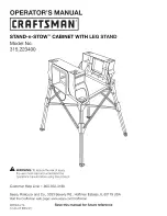
315.223400
Brand: Craftsman Pages: 6
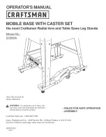
22283A
Brand: Craftsman Pages: 4

TMK-4000L
Brand: Crestron Pages: 12

NEC W32-70
Brand: NEC Pages: 4


