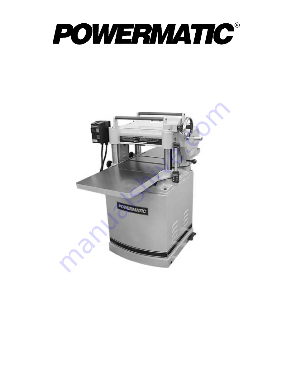
background image


OWNER’S MANUAL 

Model 15S Planer 


WMH TOOL GROUP
 

Consumer Woodworking Division 
2420 Vantage Drive 
Elgin, IL 60123 
Ph: 888-804-7129 

 Fax: 800-274-6840 

E-mail: [email protected] 

M-0460286     10/03 

www.wmhtoolgroup.com                                                            


Copyright © WMH Tool Group 


Summary of Contents for 15S

Page 1: ...l 15S Planer WMH TOOL GROUP Consumer Woodworking Division 2420 Vantage Drive Elgin IL 60123 Ph 888 804 7129 Fax 800 274 6840 E mail powermatic wmhtoolgroup com M 0460286 10 03 www wmhtoolgroup com Copyright WMH Tool Group ...

Page 2: ...egligence or accidents normal wear and tear repair or alterations outside our facilities or to a lack of maintenance WMH TOOL GROUP LIMITS ALL IMPLIED WARRANTIES TO THE PERIOD SPECIFIED ABOVE FROM THE DATE THE PRODUCT WAS PURCHASED AT RETAIL EXCEPT AS STATED HEREIN ANY IMPLIED WARRANTIES OR MERCHANTIBILITY AND FITNESS ARE EXCLUDED SOME STATES DO NOT ALLOW LIMITATIONS ON HOW LONG THE IMPLIED WARRAN...

Page 3: ...reaker Outfeed Roller 18 Outfeed Roller Height 19 Infeed Roller Height 19 Chipbreaker Height 19 Chip Deflector 20 Feed Speed Control 20 Changing Accessories for Lowest Feed Speed 20 Stock Return Rollers 21 Depth of Cut 21 Maintenance 22 Lubrication 22 Gearbox Lubricant 23 Functions of the Digital Scale 24 Calibrating Using Digital Scale 25 Optional Accessories 27 Trouble Shooting Digital Scale 27 ...

Page 4: ...e so that potential kickback area is not in line with aisles doorways wash stations or other work areas Work area Keep the floor around the machine clean and free of scrap material saw dust oil and other liquids to minimize the danger of tripping or slipping Be sure the table is free of all scrap foreign material and tools before starting to cut Make certain the work area is well lighted and that ...

Page 5: ...with power on and never use the hands to clear sawdust and debris use a brush Replacement parts Use only Powermatic or factory authorized replacement parts and accessories otherwise the warranty and guarantee is null and void Misuse Do not use this Powermatic planer for other than its intended use If used for other purposes Powermatic disclaims any real or implied warranty and holds itself harmles...

Page 6: ...e approved safety glasses and or face shield toprotecteyes and use other personal safety equipment as required Do not wear gloves 6 Disconnect machine from power source before makingany adjustments or cleaning chips away from machine 7 Keep the floor around machine clean andfree from scraps sawdust oil and grease tominimize the danger ofslipping 8 Donot operate this machine while under the influen...

Page 7: ...7 FEATURES 15S Planer Fig 2 ...

Page 8: ...M 4 500 Cuts per minute 13 500 Cutterhead diameter in 2 7 8 Feed rate FPM 16 20 Dust chute diameter in 4 Motor TEFC 3HP 1Ph 230V 60Hz Overall dimensions in H x W x L 43 1 2 x 28 x 48 Net weight lbs 507 Gross weight lbs 573 NOTE The above specifications were current at the time this manual was published but because of our policy of continuous improvement Powermatic reserves the right to change spec...

Page 9: ...sion tables 1 handwheel 1 handle 4 hex wrenches 3 4 5 6mm 1 T handle hex wrench 4mm 2 open end wrenches 8 10 12 14 1 knife adjustment tool 3 bags of fasteners 1 owner s manual 1 warranty card Contents of fastener bags Fig 4 A for installing handwheel 1 direction label 1 hex nut 1 flat washer 1 key B for installing extension tables 6 hex cap screws M8 x 25 6 socket set screws M8 x 20 C for installi...

Page 10: ...es such as tables rollers cutterhead etc have been given a protective coating at the factory This should be removed with a soft cloth moistened with a good commercial solvent Do not use acetone gasoline lacquer thinner or other solvents with a low flash point Do not use an abrasive pad because it may scratch the polished cast iron surfaces CAUTION Use care when cleaning around the cutterhead area ...

Page 11: ...e table rollers or lower the table rollers completely into the table see page 14 while mounting the extension tables 3 Insert three socket set screws with a 4mm hex wrench and screw them in or out as needed until tables are level 4 Securely tighten the hex cap screws 5 Mount the second extension table to the opposite side of the planer table using the same procedure DUST HOOD Mount the hood to the...

Page 12: ... be grounded Grounding provides a path of least resistance to help divert current away from the operator in case of electrical malfunction Make sure the voltage of your power supply matches the specifications on the motor plate of the machine EXTENSION CORDS The use of an extension cord is not recommended for this machine but if one is necessary make sure the cord rating is suitable for the ampera...

Page 13: ...Fig 12 with a 17mm wrench 3 Turn the top nut on the adjustment screw to lower the motor plate which will increase the belt tension 4 Proper tension is achieved when there is slight deflection in the belt midway between the pulleys using moderate finger pressure 5 Tighten the bottom nut on the adjustment screw Fig 12 PULLEY ALIGNMENT The pulleys should be in line for proper belt operation 1 Remove ...

Page 14: ... table the range is from zero to 0 06 Fig 15 The table rollers are factory set for average planing and are parallel to the table surface If you desire to adjust the table rollers higher or lower proceed as follows 1 Disconnect machine from power source 2 Lay a straight edge across both rollers 3 On one side of the table loosen the set screws Fig 16 with a 3mm hex wrench and turn the eccentric shaf...

Page 15: ...e 2 Remove the dust hood and the top cover Remove the chip deflector Fig 27 shows the chip deflector Remove the belt guard so you can rotate the cutterhead using the pulley 3 Remove the gib screws with the T handle hex wrench shown in Fig 18 and remove each gib one at a time 4 Remove the knife and clean the cutterhead slot of any dust or debris 5 Place the new knife loosely into the slot Put the f...

Page 16: ...n the other two knives in the same fashion until all gib screws on the cutterhead are firmly tightened NOTE The purpose of this incremental tightening process is to prevent any slight deflection or warpage of the cutterhead WARNING After installing knives check again carefully Make certain all gib screws are tightened securely Failure to heed may result in personal injury 13 Re install chip deflec...

Page 17: ...bring that corner into adjustment with the other three corners NOTE Turning sprocket clockwise will increase the distance between the working table and the head casting counterclockwise will decrease the distance This adjustment is very sensitive and it should not be necessary to turn the sprocket more than one or two teeth 6 When adjustments are correct replace chain around corner sprocket slide ...

Page 18: ...spring tension of the infeed and outfeed rollers turn screws Fig 23 with a hex wrench Turn screws on both ends of infeed outfeed rollers in the same manner HEIGHT OF INFEED ROLLER CHIPBREAKER OUTFEED ROLLER The infeed roller chipbreaker and outfeed roller are adjusted at the factory The height relationship between these items and the cutterhead is crucial for accurate and safe planing The infeed r...

Page 19: ...work table any further until the outfeed roller is adjusted 5 Remove the feeler gauge and move the gauge block F Fig 26 under one end of the outfeed roller The bottom of the outfeed roller should just touch the top of the gauge block If an adjustment to the outfeed roller is necessary loosen the lock nut J Fig 26 and turn screw H Fig 26 until the outfeed roller just touches the gauge block Then ti...

Page 20: ...ated infeed roller and a solid steel outfeed roller When the feed rollers are engaged they turn to feed the stock The feed rollers slow automatically when the machine is under heavy load for best planing in all conditions The feed rollers are driven by chains and sprockets see Fig 28 which take power directly from the cutterhead through the oil bath gear box The drive chain does not need tensionin...

Page 21: ... OF CUT The cutting depth scale is a combination inch metric scale Fig 32 with a cutting range from 0 to 6 152 4mm A manual scale is mounted directly to the front column The model 15S planer also features a digital scale for easier more precise depth readings The distance of upward or downward movement is controlled by the handwheel Fig 32 Before moving the table up or down loosen the locking hand...

Page 22: ...moother Avoid any wax that contains silicone or other synthetic ingredients These materials can find their way into lumber and can make staining and finishing difficult Another option is talcum powder applied with a blackboard eraser rubbed in vigorously once a week this will fill casting pores and form a moisture barrier This method provides a table top that is slick and allows rust rings to be e...

Page 23: ... To replace the lubricant 1 Remove the drain plug A Fig 34 with a 14mm wrench Drain dirty oil thoroughly 2 Insert and tighten the drain plug A Fig 34 3 Remove filler cap B Fig 34 and fill with clean lubricant through the hole Fill until the oil reaches the top of the filler plug port for correct oil level 4 Install and tighten filler cap B Fig 34 ...

Page 24: ...displays absolute zero Moving the planer table up and down begins absolute measurement Absolute measurement is usually set based upon the distance from cutterhead to table Press ABS button no longer than 3 seconds to switch to relative mode INC will appear on the display The value shown is in relative mode Moving the table up and down will now display relative measurement MM INCH millimeters inche...

Page 25: ...asting will prevent contact between table and cutterhead However there are two relatively easy methods of establishing zero in absolute mode Method 1 uses a gauge such as a height gauge or a home made gauge block see Fig 17 If using a home made gauge block make sure it has been cut to exact specifications 1 Disconnect machine from power source 2 Turn on the digital display It turns on in absolute ...

Page 26: ...065 inches in relative measurement mode You can now plane your board with exact results Of course you can now toggle back and forth between relative and absolute mode by pressing ABS button and get both stock thickness and depth of cut readings at the same time Clearing a Jammed Board If you have to temporarily move the planer table for example to clear a jammed board use the HOLD button to rememb...

Page 27: ...oltage 1 Replace battery Locked digits 1 Haphazard memory 1 Take battery out wait thirty seconds then re insert it No display 1 Poor contact of battery 1 Improve battery contact 2 Low voltage 2 Replace battery Displays only 0000 1 Short circuit of zero setting spring 1 Remove frame and adjust spring and slider signal source Function buttons won t 1 Distortion of springs from 1 Remove frame and adj...

Page 28: ...rpen or replace Torn Grain 1 Too heavy a cut 1 Adjust proper depth of cut 2 Knives cutting against grain 2 Cut along the grain 3 Dull knives 3 Sharpen knives Rough Raised Grain 1 Dull knives 1 Sharpen knives 2 Too heavy a cut 2 Adjust proper depth 3 Moisture content too high 3 Remove high moisture content from wood by drying Rounded glossy 1 Dull knives 1 Sharpen or replace knives surface 2 Feed s...

Page 29: ...loading trips which are not electrical in nature is too heavy a cut The solution is to take a lighter cut If too deep a cut is not the problem then check the amp setting on the overload relay Match the full load amps on the motor as noted on the motor plate If amp setting is correct then there is probably a loose electrical lead Check amp setting on motor starter 4 Building circuit breaker trips o...

Page 30: ... electric motor is suspect you have two options Have a qualified electrician test the motor for function or remove the motor and take it to a quality electric motor repair shop and have it tested 8 Miswiring of the unit 8 Double check to confirm all electrical connections are correct and properly tight The electrical connections other than the motor are pre assembled and tested at the factory Ther...

Page 31: ...partment call our toll free number between 8 00 a m and 4 30 p m CST Monday through Friday Having the Model Number and Serial Number of your machine available when you call will allow us to serve you quickly and accurately Phone No 800 248 0144 Fax No 800 274 6840 If you are calling from Canada please call 800 238 4746 ...

Page 32: ...84712 Key 4 4 10 1 11 6284713 Gear 1 12 6284714 Retaining Ring STW 10 1 13 6284715 Bearing 6202Z 4 14 6284716 Retaining Ring Internal RTW 35 4 15 6284717 Sprocket 4 16 TS 1550071 Flat Washer M10 4 17 TS 1540071 Hex Nut M10 4 18 TS 1550061 Flat Washer M8 2 19 TS 1490041 Hex Cap Screw M8 25 2 20 6284722 Shaft 1 21 6284723 Tension Bracket 1 22 6284724 Sprocket 1 23 6284725 Retaining Ring STW 15 1 24 ...

Page 33: ...33 Base Assembly 15S Planer ...

Page 34: ... Lock Nut 2 7 6284738 Threaded Shaft 2 8 6284736 Lock Bushing 2 9 6284739 Knob M12 1 75P 2 10 15S 310 Cast Iron Table Extension 2 11 15S 311 Screw M3 0 6P 6L 2 12 15S 312 Screw M5 0 8P 8L 2 13 15S 313 Plate 1 14 15S 314 Digital Readout 1 15 TS 1550021 Flat Washer M4 1 16 TS 1503051 Socket Head Cap Screw M6x20 8 17 TS 1490041 Hex Cap Screw M8 25 6 18 15S 318 Screw M4 0 7P 8L 1 19 TS 1524021 Socket ...

Page 35: ...35 Table Assembly 15S Planer ...

Page 36: ...e Geared Shaft 18 22T 1 13 6284854 Gear 71T 1 14 6284855 Key 6 6 40 1 15 6284856 Gear Assembly 1 16 6284857 Spring 0 6 1 17 6284858 Steel Ball 6 1 18 6284859 Gear Shaft 1 19 6284860 Oil Shaft SC25 47 6 1 20 6284861 Bearing 6204Z 1 21 6284862 Clutch Handle 1 22 6284863 O Ring 1 23 6284864 Gearbox Cover 1 24 6284865 Knob 32 3 8 16NC 1 25 TS 1482051 Hex Cap Screw M6x25 6 26 6284867 Pin 2 27 6284868 S...

Page 37: ...37 Gearbox Assembly 15S Planer ...

Page 38: ...sher 5 16 12 11 TS 1540061 Hex Nut M8 1 25P 4 12 6284885 Pivot Bar 2 13 6284886 Spacer 1 14 TS 1503031 Socket Head Cap Screw M6x12 1 15 6284888 Tension Bolt Assembly 1 16 6284831 Hex Nut M10 1 25P 2 17 TS 0680061 Flat Washer 1 2 2 18 6284890 Wheel 4 19 TS 0060111 Hex Cap Screw 3 8 16 2 5 4 20 6284892 Locking Nut 3 8 16NC 4 21 15S 521 Locking Nut M10 1 5P 1 22 TS 1550071 Flat Washer M10 1 23 628489...

Page 39: ...39 Cabinet Assembly 15S Planer ...

Page 40: ...Screw M8 25 2 21 6284770 Key 5 5 22 2 22 6284771 Sprocket 31T 1 23 TS 1550041 Flat Washer M6 2 24 TS 1482031 Hex Cap Screw M6 16 2 25 6284774 Outfeed Roller 1 26 6284775 Sprocket 1T 1 27 6284776 Shaft 1 28 6284777 Retaining Ring TW 12 1 29 TS 1540081 Hex Nut M12 1 30 6284779 Chip Breaker 1 31 15S 231 Plate 1 32 15S 232 Screw 5 0 8P 8L 2 33 6284780 Bracket 3 34 TS 1482021 Hex Cap Screw M6 12 4 35 6...

Page 41: ...y 1 69 TS 1503021 Socket Head Cap Screw M6 10 2 70 6284814 Bracket 1 71 6284815 Shaft 1 72 6284818 Hanger 1 73 6284819 Spring 1 2 1 74 6284720 Flat Washer 8 2 22 4 5T 1 75 TS 1503031 Socket Head Cap Screw M6 12 3 76 6284820 Warning Label 1 77 6284821 Lubrication Label 2 78 15S 278 Warning Label 1 79 6284823 Speed Label 1 80 6284824 Motor Pulley 1 81 6284830 Handwheel Direction Label 1 82 6284712 K...

Page 42: ...42 Head Assembly 15S Planer ...

Page 43: ...43 ELECTRICAL SCHEMATIC 15S Planer Single phase 230 volt ...

Page 44: ...44 ...

Page 45: ... grease Clean table surface If rusted use paste mixture of household ammonia a good commercial detergent and 000 steel wool Wash surface down with hot soapy water rinse and dry thoroughly Coat surface with talcum powder rubbing briskly into surface with a clean blackboard eraser Check blade condition should be sharp and free of nicks or grooves Check belt condition Replace as needed Dress with bel...

Page 46: ...46 ...

Page 47: ...47 ...

Page 48: ...48 WMH Tool Group 2420 Vantage Drive Elgin IL 60123 Phone 888 804 7129 Fax 800 274 6840 E mail powermatic wmhtoolgroup com Website www wmhtoolgroup com ...

Reviews: