background image

 MODEL G0453Z/G0454Z

15" & 20" MOBILE PLANER

w/SPIRAL CUTTERHEAD

OWNER'S MANUAL

COPYRIGHT © APRIL, 2009 BY GRIZZLY INDUSTRIAL, INC., REVISED JUNE, 2018 (HE)

WARNING: NO PORTION OF THIS MANUAL MAY BE REPRODUCED IN ANY SHAPE

 OR FORM WITHOUT THE WRITTEN APPROVAL OF GRIZZLY INDUSTRIAL, INC.

(FOR MODELS MANUFACTURED SINCE 1/09) #TS11416  PRINTED IN CHINA
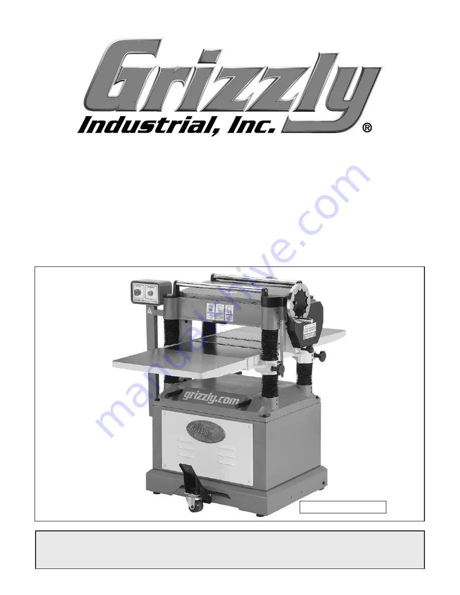
Model G0454Z Shown

Summary of Contents for G0453Z

Page 1: ... COPYRIGHT APRIL 2009 BY GRIZZLY INDUSTRIAL INC REVISED JUNE 2018 HE WARNING NO PORTION OF THIS MANUAL MAY BE REPRODUCED IN ANY SHAPE OR FORM WITHOUT THE WRITTEN APPROVAL OF GRIZZLY INDUSTRIAL INC FOR MODELS MANUFACTURED SINCE 1 09 TS11416 PRINTED IN CHINA Model G0454Z Shown ...

Page 2: ...ng grinding tool integrity and the usage of personal protective equipment The manufacturer will not be held liable for injury or property damage from negligence improper training machine modifications or misuse Some dust created by power sanding sawing grinding drilling and other construction activities contains chemicals known to the State of California to cause cancer birth defects or other repr...

Page 3: ...54Z Headstock 54 G0454Z Table 57 G0454Z Columns 58 G0454Z Gearbox 59 G0454Z Stand 60 G0454Z Label Placement 62 WARRANTY AND RETURNS 65 INTRODUCTION 2 Manual Accuracy 2 Contact Info 2 Machine Description 2 Identification 3 Internal Components 4 G0453Z Machine Data Sheet 5 G0454Z Machine Data Sheet 7 SECTION 1 SAFETY 9 Safety Instructions for Machinery 9 Additional Safety Instructions for Planers 11...

Page 4: ...strial Inc C O Technical Documentation Manager P O Box 2069 Bellingham WA 98227 2069 Email manuals grizzly com Contact Info Machine Description Manual Accuracy We are proud to offer this manual with your new machine We ve made every effort to be exact with the instructions specifications drawings and photographs of the machine we used when writ ing this manual However sometimes errors do happen an...

Page 5: ...llers NOTICE If you have never used this type of machine or equipment before WE STRONGLY RECOMMEND that you read books review industry trade magazines or get formal training before beginning any projects Regardless of the content in this section Grizzly Industrial will not be held liable for accidents caused by lack of training Cabinet Access Panel Front Extension Wing Rear Extension Wing Table Lo...

Page 6: ...o the dust port D Chip Deflector Directs chips into the dust hood E Cutterhead Holds the indexable car bide inserts that remove material from the workpiece A C B E H H I F F Pressure Bar Stabilizes the workpiece as it leaves the cutterhead and assists in deflect ing wood particles toward the dust hood G0454Z only G Outfeed Roller Pulls the workpiece through the planer H Table Rollers Provide a rol...

Page 7: ...tprint Length x Width 22 1 2 x 22 in Shipping Dimensions Type Wood Crate Content Machine Weight 672 lbs Length x Width x Height 36 x 29 x 47 in Must Ship Upright Yes Electrical Power Requirement 240V Single Phase 60 Hz Prewired Voltage 240V Full Load Current Rating 15A Minimum Circuit Size 20A Connection Type Cord Plug Power Cord Included Yes Power Cord Length 5 ft Power Cord Gauge 12 AWG Plug Inc...

Page 8: ...ter Insert Type Indexable Carbide Cutter Insert Size Length 14 mm Cutter Insert Size Width 14 mm Cutter Insert Size Thickness 2 mm Table Info Table Headstock Movement 8 in Table Bed Size Length 20 in Table Bed Size Width 15 in Table Bed Size Thickness 1 3 4 in Number of Bed Rollers 2 Floor to Table Height 27 35 in Roller Ext Table Size Length 42 in Roller Ext Table Size Width 15 in Roller Ext Tabl...

Page 9: ...er Requirement 240V Single Phase 60 Hz Prewired Voltage 240V Full Load Current Rating 25A Minimum Circuit Size 30A Connection Type Cord Plug Power Cord Included Yes Power Cord Length 6 1 2 ft Power Cord Gauge 12 AWG Plug Included Yes Included Plug Type L6 30 Switch Type Button Controls w Magnetic Switch Protection Motors Main Horsepower 5 HP Phase Single Phase Amps 19A Speed 3450 RPM Type TEFC Cap...

Page 10: ... 25 3 4 in Table Bed Size Width 20 in Table Bed Size Thickness 1 3 4 in Number of Bed Rollers 2 Floor to Table Height 26 1 2 34 1 2 in Roller Ext Table Size Length 55 1 2 in Roller Ext Table Size Width 20 in Roller Ext Table Size Thickness 1 3 4 in Construction Table Precision Ground Cast Iron Body Cast Iron Stand Steel Cutterhead Assembly Steel Infeed Roller Serrated Steel Outfeed Roller Rubber C...

Page 11: ... WEARING PROPER APPAREL Do not wear clothing apparel or jewelry that can become entangled in moving parts Always tie back or cover long hair Wear non slip footwear to avoid accidental slips which could cause a loss of workpiece control HEARING PROTECTION Always wear hear ing protection when operating or observiing loud machinery Extended exposure to this noise without hearing protection can cause ...

Page 12: ... poorly lit areas Keep work area clean dry and well lighted to mini mize risk of injury Safety Instructions for Machinery APPROVED OPERATION Untrained operators can be seriously hurt by machinery Only allow trained or properly supervised people to use machine When machine is not being used dis connect power remove switch keys or lock out machine to prevent unauthorized use especially around childr...

Page 13: ...aner DO NOT plane MDF plywood laminates or other synthetic materials that can break up inside the planer and cause injury hazards 7 GRAIN DIRECTION Planing across the grain is hard on the planer and may cause kickback Always plane in the same direction or at a slight angle with the wood grain 8 LOOKING INSIDE PLANER Wood chips fly around inside the planer at a high rate of speed during operation T...

Page 14: ...rocution or fire could result if machine is not grounded and installed in compliance with electrical codes Compliance MUST be verified by a qualified electrician Power Connection Device The type of plug required to connect your machine to power depends on the type of service you cur rently have or plan to install We recommend using the plugs shown in Figure 3 Extension Cords Using extension cords ...

Page 15: ... your machine and inspect it If you discover the machine is damaged please imme diately call Customer Service at 570 546 9663 for advice Save the containers and all packing materials for possible inspection by the carrier or its agent Otherwise filing a freight claim can be difficult When you are completely satisfied with the condi tion of your shipment inventory the contents Unpacking The Model G...

Page 16: ...m Handwheel 1 Hex Bolts M6 1 x 10 Dust Hood 3 Cap Screws M8 1 25 x 20 Dust Hood 3 Flat Washers 6mm Dust Hood 6 Hex Nuts M6 1 Dust Hood 3 Hex Wrenches 2 5 3 4 6mm 1 Each Wrenches 10 12 14 17 17 19mm 1 Each SUFFOCATION HAZARD Immediately discard all plas tic bags and packing materi als to eliminate choking suf focation hazards for children and animals Figure 4 Model G0453 G0454 inventory B C D E F G...

Page 17: ...event corrosion during shipment Remove this protective coating with a solvent cleaner or degreaser such as shown in Figure 5 Avoid chlorine based solvents such as acetone or brake parts cleaner that may damage painted sur faces Always follow the manufacturer s instruc tions when using any type of cleaning product You MUST clean the cutterhead remove the top cover table feed rollers and the exten s...

Page 18: ...ing installed Model G0454 shown Set Screws Hex Bolts Flat Washers 2 Attach the table extension wings to the planer table with 3 M8 1 25 x 30 hex bolts 8mm lock washers and 8mm flat washers as shown in Figure 8 but do not fully tighten the bolts at this time 3 Using a straightedge as a guide and the set screws for leveling control position the extension wings evenly with the table then fully tighte...

Page 19: ...d to reach into the dust hood to hold the hex nuts while tightening the hex bolts Model G0454Z Attach the dust hood with the provided 6 M6 1 x 12 flange bolts 9 Remove the hex bolt and hex nut that are pre installed in the foot pedal bracket see Figure 11 Figure 11 Foot pedal and caster installed Hex Bolt Nut Bracket Foot Pedal Caster Pin E Clip Washers 10 Align the holes of the caster assembly an...

Page 20: ...t or purchase a good dust collection how to book Check Gearbox Oil It is critical that you make sure there is oil in the gearbox before proceeding with the test run Refer to the Lubrication instructions for the gearbox on Page 30 for more details on which type of oil to use how much to use and where to put it GEARBOXES MUST BE FILLED WITH OIL NO OIL SHIPPED WITH MACHINE Requires 80W 90W or Equival...

Page 21: ...hine 3 Make sure the gearbox has the correct amount of oil refer to Gearbox Oil on Page 30 for detailed instructions Figure 13 Resetting the switch 5 Pull the feed rate control knob out to engage the feed rollers in the low speed refer to Feed Rate on Page 24 for detailed instruc tions 6 Verify that the machine is operating correctly by pushing the ON button When operating correctly the machine ru...

Page 22: ...nvenience the adjustments listed below have been performed at the factory However because of the many variables involved with shipping we recommend that you at least verify the following adjustments to ensure the best possible results from your new machine Step by step instructions for these adjustments can be found in the SERVICE section starting on Page 31 Factory adjustments that should be veri...

Page 23: ...basic controls of your planer A Magnetic ON OFF Switch Starts stops the planer B Return Rollers Provide a convenient meth od for returning workpieces to the infeed side of the planer C Table Height Handwheel Controls the ele vation of the table under the cutterhead D Feed Rate Control Knob Switches the feed rollers between high and low feed rates or in the center position stops the feed rollers E ...

Page 24: ...ne both faces of the workpiece so that they will be parallel with one another This overview gives you the basic process that happens during an operation with this machine Familiarize yourself with this process to better understand the remaining parts of the Operation section To complete a typical operation the operator does the following 1 Makes sure the workpiece is clean and free of any defects ...

Page 25: ...an become dislodged during the planing opera tion Large knots can cause kickback and machine damage Always choose workpieces that do not have large loose knots when plan ing Wet or Green Stock Avoid planing wood with a high water content Wood with more than 20 moisture content or wood exposed to excessive moisture such as rain or snow will plane poorly and cause excessive wear to the cutterhead an...

Page 26: ...0 Cedar 900 Sycamore 770 Douglas Fir 660 Chestnut 540 Hemlock 500 White Pin 420 Basswood 410 Eastern White Pine 380 Balsa 100 Figure 15 Janka Hardness Rating for some common wood species Feed Rate NOTICE Only change the feed rate when the planer is running but DO NOT attempt to change the feed rate during any cutting operations or damage to the gearbox will result The infeed and outfeed rollers mo...

Page 27: ...planing depth of cut is controlled by using the table height handwheel on the right side of the machine Rotating the handwheel clockwise raises the table The depth of cut is read directly from the inch mil limeter scale on the front of the planer as shown in Figure 17 One complete turn of the handwheel raises or lowers the table approximately 1 16 The range of material thickness that can be planed...

Page 28: ...e the eccentric adjustment hex bolts to raise or lower the bed rollers until they are the desired height above the table surface 5 Verify that both sides of each roller are at the same height then re tighten the four set screws to secure the setting 6 Re check the roller heights to make sure they did not change when you secured them If the roller heights are not correct repeat this procedure until...

Page 29: ...om 26 to 44 0º 45º 150 lb capacity G8984 Single Roller Stand Adjusts from 26 5 8 to 45 250 lb capacity G8985 5 Roller Stand Adjusts from 26 to 445 8 250 lb capacity These super heavy duty roller stands feature con venient hand knobs for fast height adjustment Figure 21 SHOP FOX Roller Stands G8983 G8985 G8984 T21348 Carbide Indexable Inserts 10 Pk Figure 22 T21348 solid carbide inserts 10 Pk G1029...

Page 30: ...eck repair replace worn or damaged wires Resolve any other unsafe condition Every 40 Hours of Operation Lubricate the table columns and leadscrews Page 29 Clean vacuum the dust buildup from inside the cabinet and off motor Schedule Vacuum excess wood chips and sawdust from the outside of the machine inside the cabinet and off the motor Protect the unpainted cast iron sur faces on the table by wipi...

Page 31: ...ing as shown in Figure 24 Figure 24 Lubrication locations for the feed roller bushings Lubricate Here Columns and Leadscrews The table rides on the columns and is moved by the rotation of the leadscrews inside the columns For the Model G0454Z loosen the dust sleeve see Figure 25 to access the columns and lead screws Apply a thin coat of SAE 30W oil to the outside surface of the columns and brush o...

Page 32: ... the machine as shown in Figure 28 Remove the table height handwheel and the safety covers attached to the inside of the drive chain cover then remove the cover to access these parts Use shop rags to clean away any debris and grime then brush on a light coat of SAE 30W oil to the chain and sprockets Figure 28 Drive chain and sprockets Gearbox Oil The gearbox oil should be changed after the first 2...

Page 33: ... switch 10 Test replace if faulty 11 Adjust replace centrifugal switch 12 Test repair replace Machine stalls or is underpowered 1 Feed rate too fast 2 Workpiece material not suitable 3 Dust collection ducting problem 4 Motor overheated 5 Machine undersized for task 6 V belt s slipping 7 Motor wired incorrectly 8 Plug receptacle at fault 9 Run capacitor at fault 10 Pulley sprocket slipping on shaft...

Page 34: ... 25 2 Adjust the rear extension wing set screws to make the extension level with the main table Page 16 3 Raise the height of the chip breaker or pressure bar Page 38 4 Use an assistant or roller beds stands to properly support the workpiece as it leaves the planer Workpiece stops slows in the middle of the cut 1 Depth of cut too deep 2 Pitch and glue build up on planer components 3 One or both of...

Page 35: ...r pressure bar set unevenly 3 Bed rollers set too high or low not even with each other 4 Insert s not properly installed 5 Worn cutterhead bearings 1 Reduce feed rate Page 24 2 Adjust the height of the chip breaker or pressure bar Page 38 3 Properly adjust the bed roller height Page 25 4 Remove insert s then properly clean and install Page 34 5 Replace cutterhead bearings Glossy surface 1 Inserts ...

Page 36: ...utward If all four insert cutting edges have been used replace the insert with a new one Always position the reference dot in the same position when installing a new insert to aid in the rotational sequencing 7 Lubricate the Torx screw threads with a very small amount of light machine oil wipe the excess off and torque the screw to 50 55 inch pounds Note If too much oil is applied to the threads t...

Page 37: ...re handling them Figure 32 Front cabinet cover removed to expose the motor Motor Mount Hex Nuts 4 If the V belts need to be replaced raise the motor to release the belt tension refer to the next step for instructions roll them off the pulleys then replace them as a matched set of three 5 To adjust the V belt tension loosen the top motor mount hex nuts see Figure 32 then adjust the bottom hex nuts ...

Page 38: ... the belt cover then use the straightedge to check pul ley alignment as shown in Figure 34 If the pulleys are not in the same plane loosen the cap screw or hex bolt securing the pulley to the shaft then adjust the pul leys in or out until they are even with each other If the pulleys are not parallel loosen the four motor mount hex nuts then rotate the motor on its mount until they are parallel 3 R...

Page 39: ... Table height idler sprocket and lock bolts viewed from underneath the planer base Lock Bolts Idler Sprocket NOTICE During the next step DO NOT let the chain fall off the sprockets It can be very difficult to return the chain to its proper location on the sprockets without changing the table adjustments Note The goal in the next step is to remove looseness in the chain without putting tension on i...

Page 40: ... Rotacator dial to zero Figure 37 Using a Rotacator to find BDC It is essential that the feed rollers chip breaker and pressure bar are set at the correct distance below the cutterhead to ensure that the workpiece moves through the planer evenly and the correct distance from the cutterhead To ensure accurate results and make the adjust ment process quicker and easier we recommend using a Rotacator...

Page 41: ... nuts 10 Keeping the same zero reference on the Rotacator dial from Step 5 repeat Steps 7 10 for the outfeed roller but adjust it until it is 0 020 below the BDC of the cutterhead insert Figure 38 Infeed roller bushing block and height adjustment controls Roller Bushing Block Jam Nut Set Screw 11 Use the same zero reference on the Rotacator dial from Step 5 perform similar steps as described above...

Page 42: ...s of the table as illustrated in Figure 41 36 Figure 41 Wood blocks properly positioned on the planer table 5 Remove the dust hood top cover and belt cover 6 Use a feeler gauge to adjust the table until there is a 0 040 gap between the wood blocks and a cutterhead insert at BDC which is the recommended distance for the infeed roller below the cutterhead 7 Lock the table in place as the wood blocks...

Page 43: ...if you are planing milled lumber with a relatively consistent surface use less spring tension If you are plan ing rough lumber with inconsistent surfaces use greater spring tension to keep the stock moving through the planer If the workpiece consistently stops feeding during operation the roller spring tension may need to be increased If the roller is leaving indents in the wood as it leaves the p...

Page 44: ...ended across the head casting and in front of the infeed roller as shown in Figure 45 This design allows the workpiece to easily enter the planer but reduces the risk of kickback by digging into the workpiece if it moves backward Figure 45 Anti kickback fingers Anti Kickback Fingers Check the anti kickback fingers regularly to ensure that they swing freely and easily If not first clean them with a...

Page 45: ...s disconnected or connected during any wiring task to ensure tight connections 4 WIRE COMPONENT DAMAGE Damaged wires or components increase the risk of serious personal injury fire or machine damage If you notice that any wires or components are damaged while performing a wiring task replace those wires or compo nents before completing the task 5 MODIFICATIONS Using aftermarket parts or modifying ...

Page 46: ...13no 14no A2 A1 Ground Ground Hot Hot L6 20 PLUG as recommended 220 VAC Contactor NHD C09 D 220V OL Relay NHD NTH17 14 17A ON Switch Top STOP Reset Switch 2 4 1 3 5 2 4 1 3 5 Ground Ground 220V MOTOR Start Capacitor 250MFD 250VAC Run Capacitor 40MFD 450VAC 2T1 6T3 4T2 97 MAN AUTO 98 15 16 17 14 95 96 R O R G0453Z Wiring Diagram wiring diagram g0453z ...

Page 47: ... 5L3 2T1 4T2 6T3 13no 14no A2 A1 Ground Ground Hot Hot L6 30 PLUG as recommended 220 VAC Contactor NHD C25 D 220V OL Relay NHD NTH 28 24 28A ON Switch Top STOP Reset Switch 2 4 1 3 5 2 4 1 3 5 Ground Ground 220V MOTOR Start Capacitor 300MFD 300VAC Run Capacitor 60MFD 400VAC 2T1 6T3 4T2 97 MAN AUTO 98 25 26 28 27 24 95 96 R O R G X Y wiring diagram g0545z ...

Page 48: ... 38 39 40 42 41 45 51 52 53 54 55 56 57 58 59 60 61 62 63 65 67 64 68 69 70 71 72 74 75 76 73 78 79 1 81 85 83 84 82 87 86 88 89 90 91 92 93 94 95 99 97 98 101 104 105 106 102 96 100 103 107 21 50 108 109 77 1 77 80 49 48 48 1 48 2 79 20 23 19 22 97 98 G0453Z Headstock Breakdown SECTION 9 PARTS parts breakdown ...

Page 49: ...1 25 X 45 83 P0453Z083 ANTI KICKBACK SHAFT COLLAR 30 P0453Z030 SHAFT 84 P0453Z084 ANTI KICKBACK FINGER 31 P0453Z031 SAFETY HATCH 85 P0453Z085 ANTI KICKBACK FINGER SHAFT 32 P0453Z032 FLANGE BOLT M6 1 X 10 86 P0453Z086 SET SCREW M8 1 25 X 16 33 P0453Z033 IDLER PULLEY BRACKET ASSY 87 P0453Z087 HEX BOLT M6 1 X 16 34 P0453Z034 IDLER MOUNTING SHAFT 88 P0453Z088 FLAT WASHER 6MM 35 P0453Z035 IDLER BRACKET...

Page 50: ...453Z208 LOCK BAR 202 P0453Z202 ROLLER 209 P0453Z209 FEMALE KNOB M12 1 75 203 P0453Z203 BALL BEARING 608 2RS 210 P0453Z210 EXTENSION WING 204 P0453Z204 ECCENTRIC SHAFT 211 P0453Z211 LOCK WASHER 8MM 205 P0453Z205 SET SCREW M6 1 X 16 212 P0453Z212 FLAT WASHER 8MM 206 P0453Z206 GIB 213 P0453Z213 HEX BOLT M8 1 25 X 30 207 P0453Z207 WEDGE DOG 214 P0453Z214 SET SCREW M8 1 25 X 20 ...

Page 51: ... COLUMN A 321 P0453Z321 FLAT WASHER 10MM 306 P0453Z306 BALL BEARING 6302Z 322 P0453Z322 HEX NUT M10 1 5 307 P0453Z307 INT RETAINING RING 42MM 323 P0453Z323 BRACKET 308 P0453Z308 COLUMN B 324 P0453Z324 EXT RETAINING RING 15MM 309 P0453Z309 INT RETAINING RING 40MM 325 P0453Z325 HEX BOLT M8 1 25 X 20 310 P0453Z310 SET SCREW M10 1 5 X 12 326 P0453Z326 IDLER SPROCKET 311 P0453Z311 LEADSCREW A 327 P0453...

Page 52: ... P0453Z428 GEARBOX 408 P0453Z408 GEAR SHAFT A 429 P0453Z429 HEX BOLT M8 1 25 X 50 409 P0453Z409 BALL BEARING 6201ZZ 430 P0453Z430 OIL PLUG 410 P0453Z410 GEAR A 431 P0453Z431 FLANGE COVER 411 P0453Z411 KEY 5 X 5 X 14 432 P0453Z432 CAP SCREW M5 8 X 12 412 P0453Z412 SHAFT B 433 P0453Z433 OIL SEAL 25 X 40 X 10 413 P0453Z413 BALL BEARING 6201ZZ 434 P0453Z434 PIN 5 X 10 414 P0453Z414 GEAR B 435 P0453Z43...

Page 53: ... 517 515 505 509 520 522 504 502 551V2 552 553 554 523 528 525 526 527 524 556 558 560 559 557 562 561 564 563 565 501 510 512 511 545 544 543 542 541 540 539 536 535 534 533 532 531 530 550 537 538 546 547 548 549 549A 503 508 529 555 518 2 518 1 518 3V2 518 5V2 518 4V2 551 3 551 2 551 4 551 5 551 1 ...

Page 54: ...0453Z549A PEDAL ASSEMBLY 518 2 P0453Z518 2 MOTOR FAN 550 P0453Z550 EXT RETAINING RING 9MM 518 3V2 P0453Z518 3V2 S CAPACITOR 250M 250V 1 3 4 X 3 1 2 551V2 P0453Z551V2 MAGNETIC SWITCH ASSY V2 01 11 518 4V2 P0453Z518 4V2 R CAPACITOR 40M 450V 1 3 8 X 2 3 8 551 1 P0453Z551 1 MAG SWITCH COVER ASSEMBLY 518 5V2 P0453Z518 5V2 JUNCTION BOX V2 05 08 551 2 P0453Z551 2 CONTACTOR NHD C 09D 230V 518 6 P0453Z518 ...

Page 55: ...ls REF PART DESCRIPTION REF PART DESCRIPTION 602 P0453Z602 GLASSES RESPIRATOR LABEL 609 P0453Z609 GRIZZLY LOGO PLATE 603V2 P0453Z603V2 MACHINE ID LABEL CSA V2 08 12 610 P0453Z610 GRIZZLY GREEN TOUCH UP PAINT 604 P0453Z604 READ MANUAL LABEL 611 P0453Z611 GRIZZLY PUTTY TOUCH UP PAINT 605 P0453Z605 HEARING PROTECTION LABEL 612 P0453Z612 MODEL NUMBER LABEL 606 P0453Z606 CUTTERHEAD DANGER LABEL 613 P04...

Page 56: ... 26 24 28 29 30 32 31 33 27 71 34 35 36 38 39 37 40 41 43 42 46 47 44 45 55 56 57 58 59 60 61 62 63 64 65 66 67 68 70 72 69 73 74 75 76 77 79 80 81 78 82 83 84 85 1 86 88 87 92 90 91 89 94 93 95 96 97 98 99 101 100 102 106 104 105 108 112 113 114 110 109 103 107 111 115 85 84 1 54 53 118 119 53 1 53 2 104 105 ...

Page 57: ...1 25 X 20 27 P0454Z027 ROLL PIN 6 X 20 75 P0454Z075 SET SCREW M6 1 X 20 28 P0454Z028 REAR SAFETY HATCH 76 P0454Z076 HEX NUT M6 1 29 P0454Z029 FRONT SAFETY HATCH 77 P0454Z077 PRESSURE PLATE SHAFT 30 P0454Z030 FLANGE BOLT M6 1 X 10 78 P0454Z078 SET SCREW M6 1 X 16 31 P0454Z031 IDLER PULLEY BRACKET ASSY 79 P0454Z079 CHIP BREAKER 32 P0454Z032 IDLER MOUNTING SHAFT 80 P0454Z080 SET SCREW M6 1 X 20 33 P0...

Page 58: ... FLAT WASHER 6MM 111 P0454Z111 COGGED V BELT MX 60 101 P0454Z101 HEX BOLT M6 1 X 12 112 P0454Z112 BELT COVER 102 P0454Z102 CUTTERHEAD PULLEY MX 113 P0454Z113 DON T REMOVE COVER LABEL 103 P0454Z103 MOTOR PULLEY MX V2 09 07 114 P0454Z114 STAR KNOB M8 1 25 104 P0454Z104 CUTTER PULLEY FLAT WASHER 8MM 115 P0454Z115 OIL LEVEL LABEL 105 P0454Z105 HEX BOLT M8 1 25 X 25 118 P0454Z118 DRIVER BIT TORX T20 10...

Page 59: ... P0454Z208 LOCK BAR 202 P0454Z202 ROLLER 209 P0454Z209 FEMALE KNOB M12 1 75 203 P0454Z203 BALL BEARING 6201ZZ 210 P0454Z210 EXTENSION WING 204 P0454Z204 ECCENTRIC SHAFT 211 P0454Z211 LOCK WASHER 8MM 205 P0454Z205 SET SCREW M6 1 X 12 212 P0454Z212 FLAT WASHER 8MM 206 P0454Z206 GIB 213 P0454Z213 HEX BOLT M8 1 25 X 35 207 P0454Z207 WEDGE DOG 214 P0454Z214 SET SCREW M8 1 25 X 20 ...

Page 60: ...EX NUT M10 1 5 306 P0454Z306 BALL BEARING 6202ZZ 323 P0454Z323 IDLER BRACKET ASSY 307 P0454Z307 INT RETAINING RING 35MM 324 P0454Z324 EXT RETAINING RING 15MM 308 P0454Z308 COLUMN B 325 P0454Z325 HEX BOLT M8 1 25 X 25 309 P0454Z309 INT RETAINING RING 38MM 326 P0454Z326 IDLER SPROCKET 310 P0454Z310 SET SCREW M10 1 5 X 12 327 P0454Z327 FLAT WASHER 8MM 311 P0454Z311 LEADSCREW A 328 P0454Z328 LIFTING P...

Page 61: ...10 1 5 428 P0454Z428 GEARBOX 408 P0454Z408 GEAR SHAFT A 429 P0454Z429 CAP SCREW M8 1 25 X 50 409 P0454Z409 BALL BEARING 6201ZZ 430 P0454Z430 OIL PLUG 410 P0454Z410 GEAR A 431 P0454Z431 FLANGE COVER 411 P0454Z411 KEY 5 X 5 X 14 432 P0454Z432 CAP SCREW M5 8 X 12 412 P0454Z412 SHAFT B 433 P0454Z433 OIL SEAL 25 X 40 X 10 413 P0454Z413 BALL BEARING 6201ZZ 434 P0454Z434 PIN 5 X 10 414 P0454Z414 GEAR B 4...

Page 62: ... 553 551 556 557 522 550 503 502 510 509 511 528 518 520 505 513 512 507 523 526 525 524 527 517 515 506 516 514 504 508 519 519 521 555 554 501 549 548 547 546 538 537 529 530 531 532 533 534 535 536 539 540 541 542 543 544 545 549A 517 2 517 1 517 3 517 5 517 4 550 3 550 2 550 4 550 5 550 1 ...

Page 63: ...517 3V2 P0454Z517 3V2 S CAPACITOR 300M 250V 549A P0454Z549A PEDAL ASSEMBLY 517 4V2 P0454Z517 4V2 R CAPACITOR 60M 450V 550V2 P0454Z550V2 MAGNETIC SWITCH MS1 35D V2 01 11 517 5 P0454Z517 5 MOTOR WIRING JUNCTION BOX 550V2 1 P0454Z550V2 1 MAG SWITCH COVER ASSY V2 07 12 517 6 P0454Z517 6 BALL BEARING 6206ZZ 550V2 2 P0454Z550V2 2 CONTACTOR NHD C 35D 220V 517 7 P0454Z517 7 BALL BEARING 6204ZZ 550 3 P0454...

Page 64: ... labels REF PART DESCRIPTION REF PART DESCRIPTION 602 P0454Z602 GLASSES RESPIRATOR LABEL 609 P0454Z609 GRIZZLY LOGO PLATE 603V2 P0454Z603V2 MACHINE ID LABEL CSA V2 08 12 610 P0454Z610 GRIZZLY GREEN TOUCH UP PAINT 604 P0454Z604 READ MANUAL LABEL 611 P0454Z611 GRIZZLY PUTTY TOUCH UP PAINT 605 P0454Z605 HEARING PROTECTION LABEL 612 P0454Z612 MODEL NUMBER LABEL 606 P0454Z606 CUTTERHEAD DANGER LABEL 61...

Page 65: ... metalworker ____ 0 2 Years ____ 2 8 Years ____ 8 20 Years ____20 Years 6 How many of your machines or tools are Grizzly ____ 0 2 ____ 3 5 ____ 6 9 ____10 7 Do you think your machine represents a good value _____Yes _____No 8 Would you recommend Grizzly Industrial to a friend _____Yes _____No 9 Would you allow us to use your name as a reference for Grizzly customers in your area Note We never use ...

Page 66: ...D LINE FOLD ALONG DOTTED LINE GRIZZLY INDUSTRIAL INC P O BOX 2069 BELLINGHAM WA 98227 2069 Place Stamp Here Name_______________________________ Street_______________________________ City______________State______Zip______ Send a Grizzly Catalog to a friend ...

Page 67: ...e tried in the State of Washington County of Whatcom We shall in no event be liable for death injuries to persons or property or for incidental contingent special or consequential damages arising from the use of our products To take advantage of this warranty contact us by mail or phone and give us all the details We will then issue you a Return Number which must be clearly posted on the outside a...

Page 68: ......

Reviews: