Quick Installation Guide
In addition to what is explained below, the safety and installation information
provided in the installation manual must be read and followed. The technical
documentation and the interface and management software for the product are
available at the website: http://www.power-one.com
AURORA CDD connects your PV System to the internet quickly and easily. It uses wireless
communication to monitor each AURORA MICRO without additional wiring. Through
the AURORA Easy View Web Portal, you can view daily and historical photovoltaic
production.
FEATURES
•
Easy setup and configuration through the internal web server
•
Data Sampling every 60 sec up to 4 sec for real-tme performance monitoring and
rapid detection of operational failure.
•
Up tp 30 AURORA MICRO inverters directly Monitored by a single CDD
•
24 hour 7 day Web-Based Monitoring
•
CDD mesh network topology ensures redundancy in communications between
CDD and MICRO and the highest design flexibility
CDD-Quick Installation Guide EN-Rev.B
01
, Wi-Fi antenna
02
,Status LED
03
, Radio antenna (MICRO inverter)
04
, Display
05
, Button pad
06
, Ethernet port
07
, RJ45 connector for RS485 serial
08
, GoGo Relay connector
09
, Power Supply connector
10
, Ethernet communication status LED
O
per
ating diagr
am
S
af
et
y and ac
ciden
t pr
ev
en
tion
D
escription of the plan
t with MICR
O in
ver
ter
A
cquisition of MICR
O in
ver
ters
Hard-wired Connection (Ethernet)
Disable the Wi-Fi connection (enabled by default) before connecting the Ethernet cable.
•
From the general menu, press any button
•
Scroll up to the “Wi-Fi enabled” screen and press
ENTER
•
Select
No
and then
ENTER
. The Wi-Fi is disabled.
•
Press the UP and DOWN buttoms simultaneously for 3 seconds, then enter the password (0010) to access to advanced menus.
•
Select
CHANGE SETTINGS > NETWORK >SELECT NETWORK > ETHERNET > PRESS ENTER
•
The CDD will restart automatically
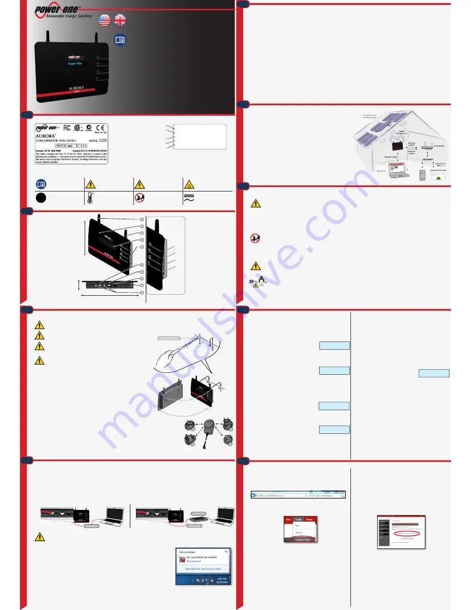
The CDD may be hardwired to the computer in either of two ways:
1. Direct to the computer using a Ethernet cable
2. Through a router using a Ethernet cable
With both methods be careful not to put the Ethernet cable in the RJ45 connector for RS-485 serial communication.
If the computer is directly connected to the CDD without any router, and if the computer is set for an automatic IP address, it is necessary to follow the procedu-
re below
•
Click on the internet icon and open the
Network and Sharing Center
•
Click Local Area Connection (LAN)
•
Click Properties
•
Click
Internet Protocol Version 4 (TCP/IPv4)
•
Click
Get the following IP address
and type a different IP address from that of the CDD (e.g. if the CDD IP
gateway address is 192.168.0.100, type
192.168.0.101)
and click
OK
The IP address of the CDD is shown on the display by pressing any button.
Once these parameters are set, input the IP address of the Web Portal (CDD) in the address bar of the Internet Browser and proceed with the commissio-
ning of the plant.
If you need to reset the Wi-Fi connection, follow the steps in reverse order.
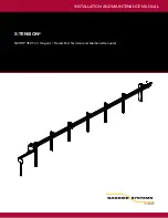
The diagram shows several AURORA MICRO inverters communicating with a
AURORA CDD, which in turn connects, by Ethernet or Wi-Fi, to a PC or a router
connected to internet.
If the device is registered on the Power-One portal (AURORA EASY VIEW web
portal), it is possible to manage and monitor the plant using a PC or Smartphone
with internet access.
Notes on the sizing of the system
Decisions about how to structure a photovoltaic system depend on a number of
factors and considerations, for example, the type of panels, the availability of space,
the future location of the system, energy production goals over the long term, etc. A
configuration program (stringtool.power-one.com) that can help size the photovoltaic
system.
C
onnec
tion t
o the PC - E
thernet
C
omp
onen
ts and o
ver
all dimensions
L
ab
els and S
ymb
ols
CDD
The labels on the CDD have the Agency marking, main technical data and identification of the equipment and manufacturer.
P/N: PPPPPPPPPPP
S/N: YYWWSSSSSS
MAC WIFI:
MAC RF:
MAC ETH:
A1:B1:C1:D1:E1:F1
A2:B2:C2:D2:E2:F2:G2:H2
A3:B3:C3:D3:E3:F3
Year(YY)/Week(WW) of manufacture
Inverter Serial Number(SSSSSS)
Inverter Part Number
Wi-Fi communication MAC addresss
RADIO communication MAC addresss*
ETHERNET communication MAC addresss
The labels attached to the equipment must not be removed, damaged, dirtied, hidden, etc.
The technical data shown in this quick installation guide does not replace those shown on the labels attached to the equipment.
Always refer to the
instruction manual
General warning
- Important safety
information
Hazardous voltage
Hot surfaces
IP20
Protection rating of
equipment
Temperature range
Forbidden signal
Direct and alternating cur-
rents, respectively
1.
3.
4.
5.
2.
6.
8.
9.
7.
*During the registration of the CDD Aurora Easy View portal the “
RADIO communica-
tion MAC address
” must be used as the identification number of the product.
• The
UP
and
DOWN
buttons are used to:
- move around a menu or to
- increase/decrease settable values
- choose settings
• The
ESC
button returns to the previous
menu.
• The
ENTER
button accesses the desired
submenu or confirms a settable value/
parameter.
• Press the
UP
and
DOWN
buttons
simultaneously to access the main menus
for STATISTICS, VIEW INFORMATION
and CHANGE SETTINGS
•
Pressing
any button
during the
normal operation (when GENERAL
INFORMATION is displayed) you
gain access to the set up basic, and
informative screens related to the CDD.
After installation phase, the CDD is connected to the PC.
The commissioning of the plant consists of the recognition of the MICRO
inverters by the CDD
•
Input the Web Portal IP address in the address bar of the browser and wait
for the display of the Local Web Portal.
In order to correctly view the Local Web Portal pages Javascript must be
active
•
In the drop-down menu select Config>Acquisition Wizard.
This menu requires Authentification
username: admin password: admin
•
Click on the icon START ACQUISITION to start scanning.
There is no timeout for the acquisition procedure. It must be stopped by
the user once all MICRO serial numbers have been acquired.
Check that all the MICRO inverters installed have been recognized. This can be
done by comparing the MAC ADDRESS detected with the ones indicated on the
cover, on the carrier box or on the removable adhesive labels used to design the
system map
.
MICRO inverters with a signal less 40 should not be assigned, as they
would be too weak. In this case it is necessary to assess whether to install
the CDD in a new position.
•
Select the AURORA MICRO inverters to be associated to CDD and press
CONFIRM
•
The next step is to define the network standard for the country of
installation (Country Standard). Then the CDD will set the standard on each
of the MICRO inverters in communication with it.
Do not set network standards that do not match the installation country.
•
The last step is the registration of the CDD on the Aurora Easy View web
portal.
•
Click on the link “
CLICK HERE TO REGISTER YOUR CDD
XX:XX:XX:XX:XX:XX:XX:XX
” to register the CDD on the Aurora Easy View
web portal.
To complete the acquisition process without registering the CDD on the Auro-
ra Easy View web portal (or to register later), click on
PLEASE CLICK HERE TO
COMPLETE
•
Click
HOME
to go back to the main screen.
•
At this point the CDD can be affixed to the wall, as all the configuration
procedures have been successfully completed.
CDD
Power-O
ne
03
04
05
10
180mm
7.08”
25mm
0.98”
09
08
07
06
02
01
150mm
5.90”
C
onnec
tion t
o the PC -
W
i-F
i
Wireless Connection (Wi-Fi)
The wireless connection of the CDD to PC must be done using a Wi-Fi router
which operates as a “bridge” for the transmission of data.
Before starting the configuration process, make sure you have a Wi-Fi router
with standard IEEE 802.11b/g, and visible SSID. In addition to unprotected
networks, WPA and WPA-2 protected protocols are supported.
•
Turn on the CDD
•
The CDD will automatically detect the local Wi-Fi
networks within reach of the device
•
On the display the number of networks detected (XX) is displayed
•
Press (ENTER) to access to the menu for the selelction of Wi-Fi network
•
The first line displays the number of networks (XX), type of protection (Open,
WPA/WPA2) and signal level (indicated with“
”). The
second line displays the name of the network (SSID).
The level of the signal may vary from one to four.
The next step of the installation depends of the type of network selected (Open,
WPA/WPA2) and the presence or absence of MAC addresses filters.
1. Configuration with open networks (Open)
A. Open networks without MAC addresses filters
• If the signal is sufficent, the CDD starts the connection to the Wi-Fi
network within a few seconds.
• A confirmation message will be displayed
• At the end of the procedure the message ”Wi-Fi Enabled” will appear.
B. Open networks with MAC addresses filters
• If the router has a filter for MAC addresses the connection fails and an
error message will be displayed.
• Afterwards the MAC address of the CDD will
be displayed. Write down the address and add
it among the enabled MAC addresses on the configuration menu of the
router.
• Once the router is configured, switch off the CDD and restart this
procedure.
2. Configuration with protected WPA/WPA2 networks
A. Protected networks without MAC addresses filters
• Before starting the connection attempt, the CDD requires an access key
of the Wi-Fi network.
By using the UP and DOWN keys to screen through the list of
characters, and choosing ENTER to confirm the selected character.
• Press ENTER two times to start the connection attempt.
• At the end of the procedure the message “Wi-Fi Enabled” will appear.
B. Protected networks with MAC addresses filters
• If the router has a filter for MAC addresses will be necessary to configure
it with the same procedure previously explained for protected networks
without MAC address filters.
• At the end of the procedure the connection
fails and on the display shows an error message.
• Afterwards the MAC address of the CDD will be
displayed. Write down the address and add it among the enabled MAC
addresses on the configuration menu of the router.
• Once the router is configured, switch off the CDD and restart this
procedure.
Autoconnection Configuration
The CDD automatically stores the parameters of the last connection (SSID
and access key). So, if autoconnection is enabled, the CDD will automatically
connect to the Wi-Fi.
To enable/disable the autoconnection function:
•
Press ESC to access the previous level of the menu
•
Press UP or DOWN up to “Autoconnection” and then ENTER
•
Press UP or DOWN to enable/disable the function.
•
Press ENTER to confirm the selection and ESC to go back to GENERAL
INFORMATION.
Installation
Wi-Fi Scanning..
(XX) Open []
SAMPLE HOUSE...
Connecting to
Wi-Fi (XX) done!
Connecting to
Wi-Fi (03) fail!
Staff authorised to carry out the installation must be specialised and experienced in this job; they must also have received suitable training on equipment of this
type
.
For Safety reasons only a qualified electrician, who has received training and / or has demostrated skills and knowledge in construction and in
operation of this unit, can install this inverter.
The installation must be done by qualified installers and/or licensed electrician
according to the applicable local code regulations
The connection of an inverter energy system to an electrical installation connected to
the electricity distribution network must be approved by the appropriate electrical
distributor.
The installation must be carried out with the equipment disconnected from the grid .
Walls of
reinforced cement
and surfaces covered in
metal
(doors, shutters, etc.) can
markedly
reduce
the reach of the device.
It is therefore advisable to undertake all the configuration
operations, before hooking the CDD and installing it in the same location and position
used during the configuration.
Also choose a place close to a socket (necessary for power) and where the lower part of CDD,
where all the connections are present, remains accessible.
•
Make 2 holes necessary to hang the CDD to the wall, using a drill with a 5 mm diameter bit. The
depth of the holes must be around 30 mm.
•
Insert anchors in the holes and tighten the countersunk screws.
•
Hang the CDD by inserting the head of the 2 screws into the holes on the back of CDD.
•
Insert the special power connector on the underside of the CDD and power the device by
connecting the AC adapter (supplied) to an electrical outlet. The power supply comes with
4 interchangeables plugs compatible with the sockets of different countries
•
In order to operate the plant, the CDD device must be connected to a
PC.
The type of connection can be:
Cabled - The device is equipped with an
Ethernet
port
Wireless -The device is equipped with a
Wi-Fi
network card
During the commissioning of the plant verify that the signal reception from the MICRO inverters and from the Wi-Fi
router is sufficient.
W
all moun
ting
A
C
G
I
CDD
Power-One
5 mm
2 x
Ø
5 mm
The plant is composed by a group of MICRO inverters that convert direct electric current from a photovoltaic module into alternating electric current and feeds it
to the electrical grid.
Photovoltaic panels transform energy from the sun into direct current (DC) electrical energy; however, to feed the grid and so that this energy can be used, it has
to be transformed into alternating current (AC). This conversion, known as DC to AC inversion, is made efficiently without using rotating parts and only through
static electronic devices.
The AURORA MICRO automatically reduces the value of the power fed into the grid in the event of adverse environmental conditions or unsuitable input voltage
values.
When used in parallel with the grid, the alternating current generated by the inverter flows directly into the domestic electrical circuit, which is in turn connected,
through a load distribution panel, to the grid. The solar energy system therefore powers all connected electrical devices, from lighting to household appliances, etc.
When the photovoltaic system is not supplying sufficient power, the power needed to ensure normal operation of the connected electrical devices is drawn from
the grid. If, on the other hand, excess power is produced, this is fed directly into the grid, so becoming available to other consumers.
In accordance with local electric utility regulations, the power produced can be sold to the grid or credited towards future consumption, bringing about a saving
of energy.
Characteristics of a system employing AURORA MICRO inverters
AURORA MICRO inverters fit one per PV panel, so each individual PV panel’s output is optimized independently of the others. This differs from a system with a
single, larger, inverter for a group of panels; in this case a single shaded or otherwise impaired panel lowers the output of the entire group.
The equipment includes safety devices suitable for the protection of components and operators.
Power-one
accepts no liability for failure to comply with the instructions for correct installation, and cannot be held responsible for the systems upstream
or downstream of the equipment it has supplied.
It is essential to provide operators with correct information. They must read and comply with the technical information given in the installer manual and in this documen-
tation. The instructions given in the installer manual do not replace the safety devices and technical data for installation and operation attached to the product,
and they certainly do not replace the safety regulations in force in the country of installation and common sense rules.
The manufacturer is willing to train staff, at its premises or on site, in accordance with conditions to be set out in a contract.
Do not use the equipment if you find any abnormal conditions.
Avoid temporary repairs. All repairs should be carried out using only genuine spare parts, which must be installed in accordance with their intended use.
Liabilities arising from commercial components are delegated to the respective manufacturers.
The equipment must be installed indoors in rooms with suitable environmental conditions (see technical characteristics).
DO NOT install outdoors! The equipment is not equipped to operate in environments with flammable or explosive conditions.
The customer and/or installer must appropriately train operators or anyone who may come near the equipment, and highlight, if necessary with
notices or other means, the hazardous areas or operations at risk. This may include: magnetic fields, hazardous voltages, high temperatures, possi-
bility of discharges, generic hazard, etc.
Ethernet cable
CDD
Power-one
Ethernet cable
Router/Switch
CDD
Power-one
Connecting to
WiFi (03) fail!
CDD
UP
DOWN
ESC
ENTER