Poulan Pro PP524A, Owner'S Manual
The Poulan Pro PP524A Owner's Manual is essential for operating and maintaining this powerful tool. Download the manual for free from our website to access detailed instructions, troubleshooting tips, and valuable information. Maximize your product's potential and ensure proper usage with this comprehensive manual.
Share
Download


Reviews:
No comments
Related manuals for PP524A
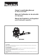
PM7650H
Brand: Makita Pages: 84

EB7650TH
Brand: Makita Pages: 35

DUB361
Brand: Makita Pages: 6

BUB143
Brand: Makita Pages: 6

BUB182Z
Brand: Makita Pages: 16

BBX7600
Brand: Makita Pages: 148

BBX7600
Brand: Makita Pages: 66

4014N
Brand: Makita Pages: 8

RBL500
Brand: Makita Pages: 9

GAST M Series
Brand: Idex Pages: 6

SCL800SM-3X
Brand: ODB Pages: 115

P55/MNF
Brand: Eurosystems Pages: 2

EBZ100-CA
Brand: Zenoah Pages: 60

311AE9P6
Brand: Cub Cadet Pages: 56

625233-01
Brand: Black & Decker Pages: 6

606432-00
Brand: Black & Decker Pages: 4

625233-00
Brand: Black & Decker Pages: 4

387739
Brand: Black & Decker Pages: 4


