background image


Package Contents 


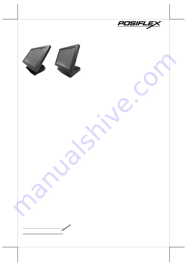
15” fanless LCD IR touch terminal with 
Gen 7E or Gen 8E base stand  (x 1) 


Power adapter   (x 1) 


Power cord    (x 1) 


User manual   (x 1) 


Recovery DVD or Information DVD (x 1) 


Product Features 


Fanless Design 


Intel 4

th

 generation Haswell CPU 


New GEN 7E foldable base that allows JIVA XT Series to be configured into 
different configurations. 


New Gen 8E foldable base that integrates internal power adaptor and powered 
USB port into the base stand. 


Mini-PCIe expansion slot 


Dual LAN Ports 


16760901010 Ver. Original


http://www.posiflex.com


XT-5415/5615 

Fanless LCD IR Touch Terminal 

User Manual 


Summary of Contents for XT-5415

Page 1: ...less Design Intel 4th generation Haswell CPU New GEN 7E foldable base that allows JIVA XT Series to be configured into different configurations New Gen 8E foldable base that integrates internal power...

Page 2: ...n 7E Base Stand Front View Rear View Side View Gen 7E Base Stand XT 5415 5615 LCD IR Touch Panel Cable Cover Base Stand Cover Cable Exit HDD Cover Power Button Brightness Adjustment Button Brightness...

Page 3: ...h Gen 8E Base Stand Front View Rear View Gen 8E Base Stand XT 5415 5615 LCD IR Touch Panel Cable Holder HDD Cover Rubber Feet with Fixing Screw Rubber Feet with Fixing Screw Cable Exit Base Stand Cove...

Page 4: ...Out MIC In Combo Jack USB 2 0 Ports USB 3 0 Ports DB9 COM Ports VGA Port CR Port LAN Ports 12V BAT Port DC IN Power Connector Power Button Brightness Adjustment Button Brightness Adjustment Button Rub...

Page 5: ...and then packaged into the box for shipping After it is unpacked you may re adjust the terminal in either low profile mode or full extended mode according to your situation Below will provide instruct...

Page 6: ...holding onto its bottom edge Then while pulling the lever backwards move the display upwards until the lever is snapped into the hook to raise the screen as shown in the below figure 4 2 Push the cab...

Page 7: ...izontal position 5 2 Support the screen with one hand holding onto its bottom edge While pulling the lever backwards move the display downwards until the lever is lifted off the hook as shown in the f...

Page 8: ...angle please be advised to keep the base stand steady with one hand to do so Do NOT press on the LCD panel while setting up the tilt angle XT 5415 5615 with Gen 8E Base Stand Please refer to the foll...

Page 9: ...ng onto its bottom edge Then while pulling the lever backwards move the display upwards until the lever is snapped into the lower hook to raise the screen as shown in the below figure 4 2 Push the cab...

Page 10: ...n to the base stand tilt your terminal down 5 2 Support the screen with one hand holding onto its bottom edge Then while pulling the lever backwards move the display upwards or downwards until the lev...

Page 11: ...nto the base stand tilt your screen up 6 2 Support the screen with one hand holding onto its bottom edge While pulling the lever backwards release the lever back to the point above the upper hook as s...

Page 12: ...terminal with its rear facing towards you and tilt the screen all the way down 2 Remove the cable cover 3 Pull outwards the locking levers with your forefingers and then remove the cover in the direc...

Page 13: ...n by the arrow 8 Properly insert the cable into the correct port on the bottom I O plate 9 Neatly arrange your cable Then make sure the cord can be held into place and passed through the cable exit af...

Page 14: ...remove the cover in the direction shown by the arrow 4 Tilt the screen to the horizontal position Thread the cables along the cable passage and then through the cable exit 5 Tilt the terminal up enoug...

Page 15: ...though the cable exit at the bottom of the base stand Installing Optional Upgrade Kits and Peripherals XT 5415 5615 is an expandable model which allows you to upgrade its own capacity by additionally...

Page 16: ...ake the AC power adapter with its rubber feet facing you Place the bottom side of the power adapter into the bottom of the power adapter compartment first and then push it down into place 3 Place two...

Page 17: ...ld the extra cable 2 as shown in the figure 7 Place back the middle compartment bracket into place and then secure it using two fixing screws 8 Lay the POS terminal on a flat surface with its rear fac...

Page 18: ...tors have to be mounted onto the top side on the rear of your POS terminal as shown in the figure As for the installation instructions along with the individual cable arrangement for the specific stan...

Page 19: ...the XT 5415 5615 Press down the power button for at least 3 seconds to power on the POS Power OFF the XT 5415 5615 In most cases press the power button of the POS to power the system off If the termin...

Page 20: ...24 x 768 Touch Function IR touch Serial Port 6 DB9 x 2 RJ45 x 2 on I O plate pin header x 2 from service window 5V support on all COM ports 12V support on COM 1 to COM 4 Parallel Port 1 via optional c...

Reviews: