background image


2017 

   FTC   Tomahawk   Instructions             


Part   1 

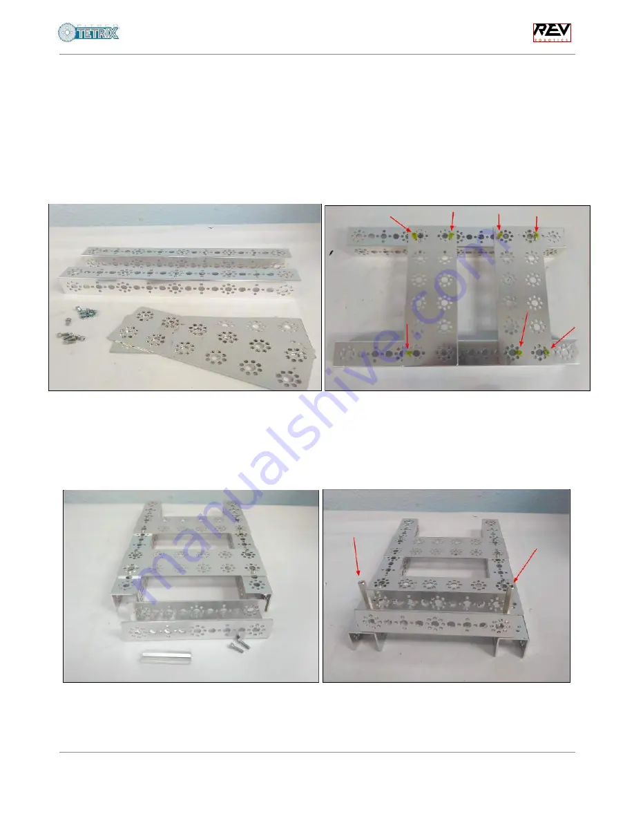
Step   1:   Chassis   frame 

Hardware: 

   288mm   channels   (x2),   flat   plates   (x2),   5/16"   socket   head   cap   screws   ( 

SHCS 

)   (x7),   kep 

nuts   (x7) 

Instructions: 

   Position   the   flat   plates   on   top   of   the   channels   and   screw   in   place.   Make   sure   that   the 

screws   (marked   in   green)   align   with   the   plates   and   channels   exactly   as   shown   in   the   photo   -   this   is 
where   the   REV   hub   will   mount   and   we   don’t   want   any   interference   from   the   screw   heads. 


Step   2:   Phone   mount 

Hardware: 

   160mm   channel   (x1),   1/2"   SHCS   (x2),   2”   stand-off   post   (x2) 

Instructions: 

   Position   the   160mm   channel   so   that   it   touches   both   ends   of   the   288mm   channels   and 

the   open   side   facing   up.   Screw   the   channel   into   place   from   the   bottom,   so   that   the   posts   stick   up. 
This   will   hold   the   robot   controller   phone.  


Srishti   Kumar,   FTC   #7172 
Lauren   PeCoy,   FTC   #8204


Patrick   R.   Michaud,   UT-Dallas 


v2017.06.2 

1


Summary of Contents for TETRIX FTC Tomahawk

Page 1: ...y as shown in the photo this is where the REV hub will mount and we don t want any interference from the screw heads Step 2 Phone mount Hardware 160mm channel x1 1 2 SHCS x2 2 stand off post x2 Instru...

Page 2: ...servo bracket onto the channel at one end and screw in place Follow screw holes indicated Step 5 Robot Arm Mount cont Hardware Arm assembly from step 4 axle hub x1 1 2 SHCS x2 Instructions Screw the...

Page 3: ...unt cont Hardware Arm assembly from step 6 bronze bushings x2 nylon spacer x2 100mm axle Instructions Add bronze bushings from the outside of the channels so the long part faces outward Now slide the...

Page 4: ...he holes indicated clamping side facing up Step 9 Driving Motor Mounts Hardware Motor mount x2 Motor Mount screws x4 kep nuts x4 Instructions Attach the motor mounts onto the base with the screws and...

Page 5: ...tor and gear into the motor mount gear first Notice how the motor shaft is not in the center of the motor This allows the motor to be rotated in its mount to get the right spacing for gears and sprock...

Page 6: ...er Hardware 1 2 SCHS x1 1 stand off post this is smaller than the ones used for the phone mount Instructions Screw the post in from the bottom so that it stands up Ensure you have the right hole spaci...

Page 7: ...he axle the axle should not extend past the screws on the wheel Once on tighten the axle hub set screw onto the flat part of the axle Step 16 Omni Wheels cont Hardware Bronze bushings x4 axle set coll...

Page 8: ...assembly and tighten the hub set screw onto the flat part of the axle Step 18 Driving Wheels cont Hardware Bronze bushings x4 axle set collar x2 Instructions Add the tires to the other side of the ro...

Page 9: ...e mounting holes are on the outside of the bracket s holes Step 20 Power Switch Hardware The power switch power switch bracket SHCS x2 nuts x2 Instructions Insert the power switch into the bracket as...

Page 10: ...battery pack Instructions Place the phone and battery in the robot in their respective places as shown Finished robot build Congratulations You have finished the robot build Now to wire it Srishti Kum...

Page 11: ...tition robot the connectors for the motor cables should be secured to the motors e g using electrical tape This ensures that the connectors do not fall off during competition Step 23 Motor wiring cont...

Page 12: ...out the arm in port 0 and the right driving motor the side with the arm in port 1 Step 24 Battery wires Hardware Anderson Powerpole to XT30 cable x1 Instructions Take the cable and attach it to the ba...

Page 13: ...switch wire There are 2 switch wires only one of them will fit Step 26 Switch wires Hardware Switch Cables x1 Instructions Take the other switch wire the one not connected to the battery and plug it...

Page 14: ...to mini USB cable x1 Instructions Attach the white USB A to mini USB cable to the hub and the black OTG cable Follow that by attaching the black OTG cable to the robot controller phone Step 28 Phone w...

Page 15: ...to use our robot as a guide Just keep in mind that it is essential that there are no loose wires near gears other moving parts because of entanglement risks The picture you see below has the wires ne...

Reviews: