Pilz PSS Series, Operating Manual
The Pilz PSS Series Operating Manual is a comprehensive and essential resource for understanding and utilizing the advanced features of our renowned PSS products. Available for free download on our website, this detailed manual provides step-by-step instructions and troubleshooting guidance to ensure efficient and safe installation and operation.
Share
Download


Reviews:
No comments
Related manuals for PSS Series

ass-vx
Brand: 3idee Pages: 7
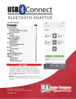
USB-Connect
Brand: U.S. Boiler Company Pages: 20

dLAN 1000 mini
Brand: Devolo Pages: 16

2071-TBMF
Brand: Allen-Bradley Pages: 2

RF802
Brand: Multitech Pages: 58
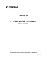
XM-UB3204
Brand: X-media Pages: 7

Powerline 1300 AV2 Adapter
Brand: TRENDnet Pages: 26

PEPWAVE MAX Adapter
Brand: peplink Pages: 20

MF1466-01
Brand: Epson Pages: 19

BT-0260
Brand: Epson Pages: 36

EHDMC10
Brand: Epson Pages: 19

OT-WL01
Brand: Epson Pages: 56

C200001 - Stylus Color 660 Inkjet Printer
Brand: Epson Pages: 67

colour 640
Brand: Epson Pages: 58

PictureMate - Compact Photo Printer
Brand: Epson Pages: 126

ELPAP10
Brand: Epson Pages: 148

OT-WL06
Brand: Epson Pages: 152

Stylus color 600
Brand: Epson Pages: 212


