background image

1

CORRECTLY      INCORRECTLY

Note: the enclosed template can be used for general positioning only
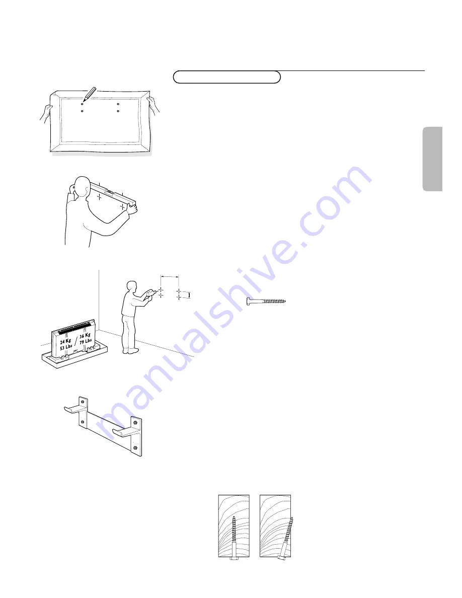
(fig. 1).

Mounting to sheetrock wall

Note: Bracket can only be used with standard 16" spaced wood wall
studs.

Bracket must be positioned so that the bracket is fastened firmly to
studs at each end.
All required hardware is included.

Note: Because the Receiver Unit’s power cord is 6’, when determining the 

Display Unit mounting location, the distance to the nearest AC power 
outlet must be considered.

&

Determine desired location to mount Display Unit.
Within this area, locate the two 16.54" spaced wall studs that must
be used as the Wall Bracket mounting location. (fig. 1 and 2)

é

With the Wall Bracket held in place, ensure it is properly leveled.
Then, mark where the four holes must be drilled. (fig. 2)

Note: Use only the holes in Bracket.

Remove the Wall Bracket, and using a 13/64" wood drill bit, drill the
four holes. (fig. 3)

Reposition the Wall Bracket, and with four lag bolts (fig. 4), secure
into place.Tighten with 13mm or 1/2" socket wrench. (fig. 5)

Note: Do not use plastic wall anchors with these lag bolts.

Note: Lag bolts must be fastened and centered securely into the stud.

Mounting Wall  Bracket

fig. 1

fig. 2

420mm /

16,54"


60,5mm /

2.38" 

fig. 3

fig. 4

fig. 5

English

Summary of Contents for 42FD9934

Page 1: ...ount Display Unit Within this area locate the two 16 54 spaced wall studs that must be used as the Wall Bracket mounting location fig 1 and 2 é With the Wall Bracket held in place ensure it is properly leveled Then mark where the four holes must be drilled fig 2 Note Use only the holes in Bracket Remove the Wall Bracket and using a 13 64 wood drill bit drill the four holes fig 3 Reposition the Wal...

Page 2: ...r to Figure 1 é With the Wall Bracket held in place ensure it is properly leveled Then mark where the four holes are to be drilled Note Use only the four outside or end holes in the Bracket Remove the Wall Bracket and reconfirm that the marks made in the previous step are located in the cavities of the concrete blocks Re locate the marks as required to ensure that they are in the cavities of the c...

Page 3: ...onfirm that the Wall Plate is level then tighten the bolts securely refer to Figure 8 Mounting to metal stud wall Determine desired location to mount the Display Unit Within this area locate the two 16 54 spaced metal wall studs that must be used as the Wall Bracket mounting location é Locate the center of both wall studs at the height that the Wall Bracket is to be mounted With the Wall Bracket h...

Page 4: ...astic retaining sleeve towards the wall until it fits into the hole in the wall This will hold the toggle bolt in the wall while the Wall Bracket is mounted refer to Figure 5 Push down on the lower plastic leg of the toggle bolt and break it off flush with the wall refer to Figure 6 Push up on the upper plastic leg of the toggle bolt and break it off flush with the wall refer to Figure 7 Install t...

Page 5: ... MAINS RS232 DVI D Y C S VHS G Y Y CVBS B Pb Cb R Pr Cr V H VGA 1 VGA 2 RC OUT VIDEO 3 AV3 VIDEO 2 AV2 VIDEO 1 AV1 ...

Page 6: ...cer P S Remember to get the most from your PHILIPS product you must return your Warranty Registration Card within 10 days So please mail it to us right now Know these safety symbols This bolt of lightning indicates uninsulated material within your unit may cause an electrical shock For the safety of everyone in your household please do not remove product covering The exclamation point calls attent...

Page 7: ...nce or C The appliance has been exposed to rain or D The appliance does not appear to operate normally or exhibits a marked change in performance or E The appliance has been dropped or the enclosure damaged 17 Tilt Stability All televisions must comply with recommended international global safety standards for tilt and stability properties of its cabinets design Do not compromise these design stan...

Page 8: ...t or output is determined by the used mode If the monitor is used in TV mode the VGA 2 connector is VGA output If the monitor is used in monitor mode the connector is VGA input or output To a TV receiver box See the handbook of the TV receiver box Connect one end of a VGA cable to the video card of the computer and the other end to the PC MAC IN connector at the rear side of the TV receiver box Fi...

Page 9: ...ert the 2 batteries supplied Type LR6 AA 1 5V The batteries supplied do not contain the heavy metals mercury and cadmium Nevertheless in many countries batteries may not be disposed of with your household waste Please check on how to dispose of batteries according to local regulations Make sure that your TV receiver box and or PC are switched on and that your PC is in the correct display mode Swit...

Page 10: ...ce and to alter a selected adjustment OK to activate your choice AV MUTE to mute the picture or restore it if the monitor is used in monitor mode When activated a green indicator starts blinking in front of the monitor q Picture format See Picture 2 menu p 7 Press the q button to switch between the different picture formats BRIGHTNESS to adjust the brightness level of the picture CONTRAST to adjus...

Page 11: ...trol to summon the main menu Picture 1 menu Brightness This control allows you to adjust the brightness level of the picture Contrast This control allows you to adjust the contrast level of the picture Color only available when the source is AV1 AV2 or AV3 YCbCr This control allows you to adjust the saturation level of the colors to suit your personal preference Color temperature This control allo...

Page 12: ...or vertical way Use the cursor left right up down to adjust é Press the OK button when done Clock frequency only available in VGA mode on VGA 1 or VGA 2 See Connect Peripheral equipment p 9 This control allows you when necessary to adjust the values of the clock frequency so that especially text can be displayed with an optimal overall sharpness Use the cursor left right to adjust Phase only avail...

Page 13: ... to set the AV3 input to HD RGB YCbCr or HD YPbPr When having selected Auto the monitor makes the selection automatically between YCbCr HD YPbPr or HD RGB See also p 9 Equipment with Component Video Output connectors Use the cursor down to select AV3 é Press the cursor right to enter the list with options Press the cursor up down to select one of the options VGA 2 This control allows you to select...

Page 14: ...with composite sync on Y or of your equipment with YCbCr output with composite sync on Y to the YPbPr resp YCbCr input VIDEO 3 AV3 IN sockets of the monitor é Connect the video cables of your equipment with RGB output with separate Horizontal and Vertical sync to the RGB input sockets and to the H and V sockets VIDEO 3 AV3 of the monitor Note when High Definition signals are inputted to the monito...

Page 15: ...e used with the monitor as stand alone This connector allows you to control the monitor via your PC as a replacement of the remote control Note This connector can also be used for dealer service tools MAINS RS232 DVI D Y C S VHS G Y Y CVBS B Pb Cb R Pr Cr V H VGA 1 VGA 2 RC OUT VIDEO 3 AV3 VIDEO 2 AV2 VIDEO 1 AV1 DVI D MAINS RS232 DVI D Y C S VHS G Y Y CVBS B Pb Cb R Pr Cr V H VGA 1 VGA 2 RC OUT V...

Page 16: ...icture performance is deteriorating Bringing the set below 6562 ft it works fine again Transportation has no influence Control of peripheral equipment The infrared radiation of the screen may influence the reception sensitivity of other peripherals Solution replace the batteries of the remote control or change position of other equipment E g keep away a wireless headphone from within a radius of 4...

Page 17: ...pyrighted a product used for commercial or institutional purposes WHERE IS SERVICE AVAILABLE Warranty service is available in all countries where the product is officially distributed by Philips Consumer Electronics Company In countries where Philips Consumer Electronics Company does not distribute the product the local Philips service organization will attempt to provide service although there ma...

Page 18: ... vente la plus près de chez vous pour obtenir un service après vente rapide et efficace Si le produit est sous garantie il suffira de présenter une preuve d achat pour bénéficier d un service sans frais Pour les produits non couverts par la garantie contactez le center le plus près de chez vous Nota Si Ud reside en una de nuestras zonas para sucursales Philips de servicio al de fábrica ver directo...

Page 19: ... recepción de productos necesitados de reparaciones comunicarse con el centro de servicio de fabrica mas cercano para estos lugares dentro de un radio de 80 a 120 km 50 a 75 millas del centro de servicio local ATLANTA Philips Factory Service 550 Franklin Road Suite F Marietta GA 30067 800 273 1501 TAMPA Philips Factory Service 1911 US Highway 301 North Tampa FL 33619 800 442 2027 SAN FRANCISCO Phi...

Reviews: