Artikelnummer / Article no.
1520 9001
Pfeuffer GmbH
Flugplatzstraße 70
97318 Kitzingen
GERMANY
Phone:
+49 9321 9369-0
Fax:
+49 9321 9369-50
E-mail:
Revision 1/17.01.2017
Internet: http://www.pfeuffer.com
Translation of the original Operating Instructions
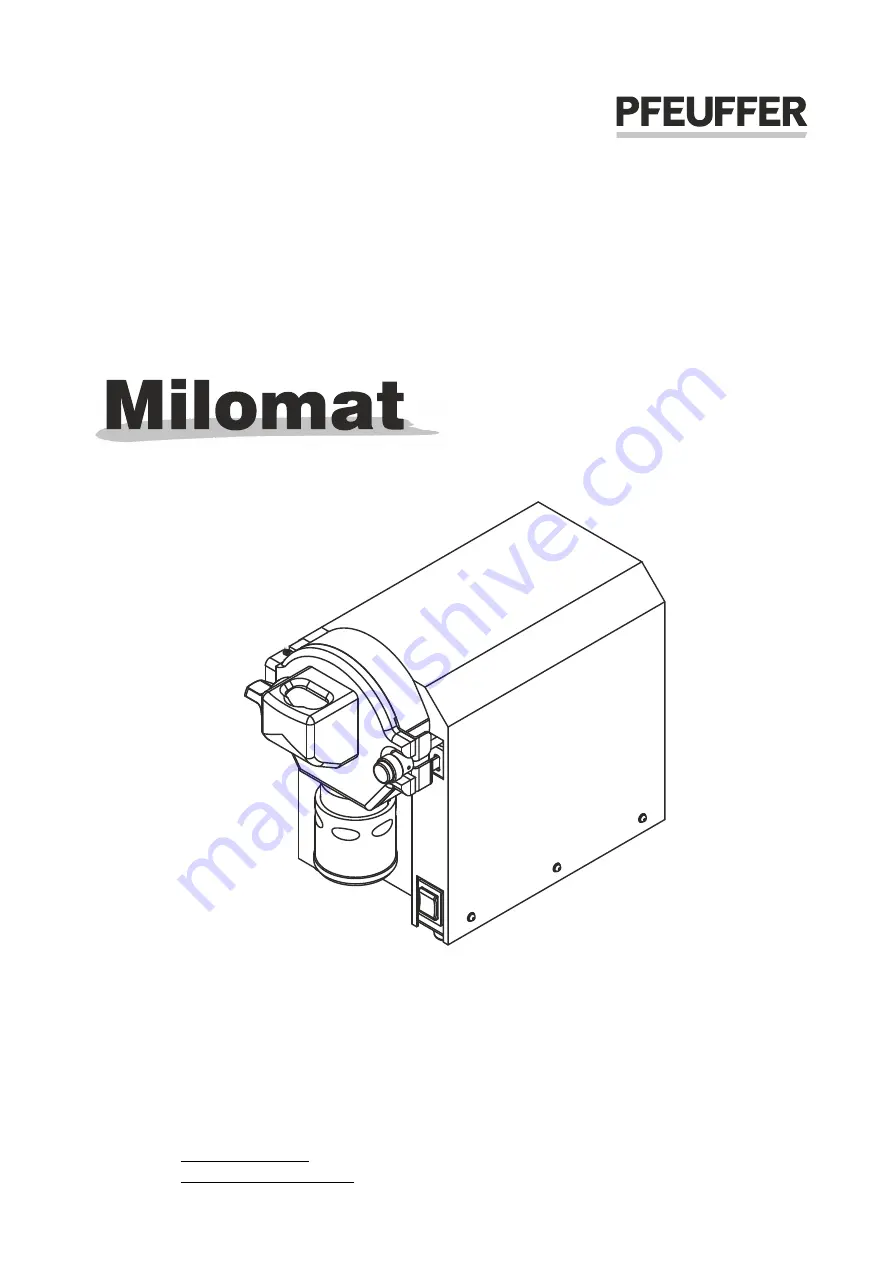
Operating Instructions
Laboratory mill