Pfaff 3819 -20/02, Instruction Manual
The Pfaff 3819 -20/02 Instruction Manual is a comprehensive guide that helps users effortlessly navigate through the functions and features of their Pfaff sewing machine. You can conveniently download this manual for free from manualshive.com, ensuring easy access whenever you need assistance in operating your machine.
Share
Download


Reviews:
No comments
Related manuals for 3819 -20/02

Panafax UF-8000
Brand: Panasonic Pages: 187
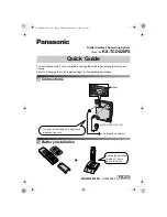
KX-TCD820FX
Brand: Panasonic Pages: 6
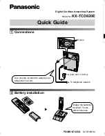
KX-TCD820E
Brand: Panasonic Pages: 6

DP-180
Brand: Panasonic Pages: 65

BR 45/22 C
Brand: Kärcher Pages: 56

BDS 43/Duo C
Brand: Kärcher Pages: 9

N 8000 Exklusive
Brand: W6 Pages: 176

BARRACUDA 200ZW
Brand: Reliable Pages: 40

QK32
Brand: Windsor Pages: 30

Windsor Chariot 3 iExtract 26 Duo
Brand: Kärcher Pages: 151

AutoHybrid
Brand: JK Audio Pages: 16

PAS20BA-BC
Brand: Powr-Flite Pages: 9

VISION:mini VCC-G21X31ACL
Brand: CIS Pages: 20

Minoltafax 1600e
Brand: Konica Minolta Pages: 127

DMN-530-4
Brand: JUKI Pages: 8

Bona PowerDrive
Brand: Kunzle & Tasin Pages: 2

private bind
Brand: Renz Pages: 8

Q35x
Brand: Octane Fitness Pages: 12


