Pepperl+Fuchs IQT1-18GM-IO-V1, Manual
The Pepperl+Fuchs IQT1-18GM-IO-V1 is a high-quality sensor with versatile capabilities. Ensure optimal performance by following the user manual, available for free download on our website. This manual provides detailed instructions for installation, maintenance, and troubleshooting. Download it from manualshive.com to make the most of your sensor.
Share
Download


Reviews:
No comments
Related manuals for IQT1-18GM-IO-V1

400 Series
Brand: B&B ARMR Pages: 28

Tri De Jetons
Brand: NATURE & DECOUVERTES Pages: 2

Stellar Series
Brand: Aqua One Pages: 4

EvoWash
Brand: Hydro Pages: 33

6ALN
Brand: MSD Pages: 2
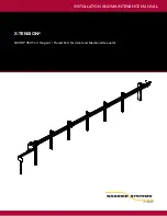
X-TENSION XTGTSM1
Brand: Barrier Systems Pages: 40

BT2300-PLUS
Brand: DHC Pages: 34

CM-0-18AA
Brand: Co2meter Pages: 14

BT 5500
Brand: EMAK Pages: 38

EAFR-101S
Brand: Eaton Pages: 32

BASIC Series
Brand: DBI SALA Pages: 40

RS-14
Brand: DV8 Pages: 10

Spicer Drive Axles
Brand: DANA Pages: 33

FaceKiosk Series
Brand: ZKTeco Pages: 47

HC574-L
Brand: HP Pages: 8

MMTC-RAM-03SL
Brand: Mishimoto Pages: 2

Swivel EA 075
Brand: Elaflex Pages: 2

TRACK WHEELS
Brand: Bontrager Pages: 4


