Payne PG8, Installation And Operating Instructions Manual
The Payne PG8 is a reliable heating and cooling system designed for ultimate comfort and energy efficiency. Ensure proper installation and operation with the comprehensive Installation And Operating Instructions Manual. Download this essential manual for free from manualshive.com to maximize the performance and longevity of your Payne PG8.
Share
Download


Reviews:
No comments
Related manuals for PG8

N9MP1
Brand: ICP Pages: 14

N9MP1
Brand: ICP Pages: 62

TM9V C Series
Brand: Johnson Controls Pages: 42

CADDY MAX CADDY WOOD ADD-ON PF01102
Brand: PSG Pages: 54

CARBOLITE GERO STF 15/450
Brand: VERDER Pages: 48

AMH95 Series
Brand: Amana Pages: 15

AMH8 33-3/8"
Brand: Amana Pages: 19

40"
Brand: Amana Pages: 19

*MEC96
Brand: Amana Pages: 60

1537M
Brand: USSC Pages: 28

000 BTU
Brand: COZY Pages: 2

CDV155D
Brand: COZY Pages: 24

737CN
Brand: Valor Pages: 23

Hot Spot 110
Brand: Zircar Pages: 13
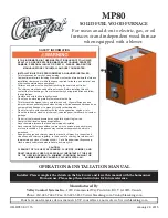
MP80
Brand: Valley Comfort Systems Pages: 36

N9MSE
Brand: ICP Pages: 56

DH1B040A9241C Series
Brand: Trane Pages: 28

DD2B060ACV32A Series
Brand: Trane Pages: 36


