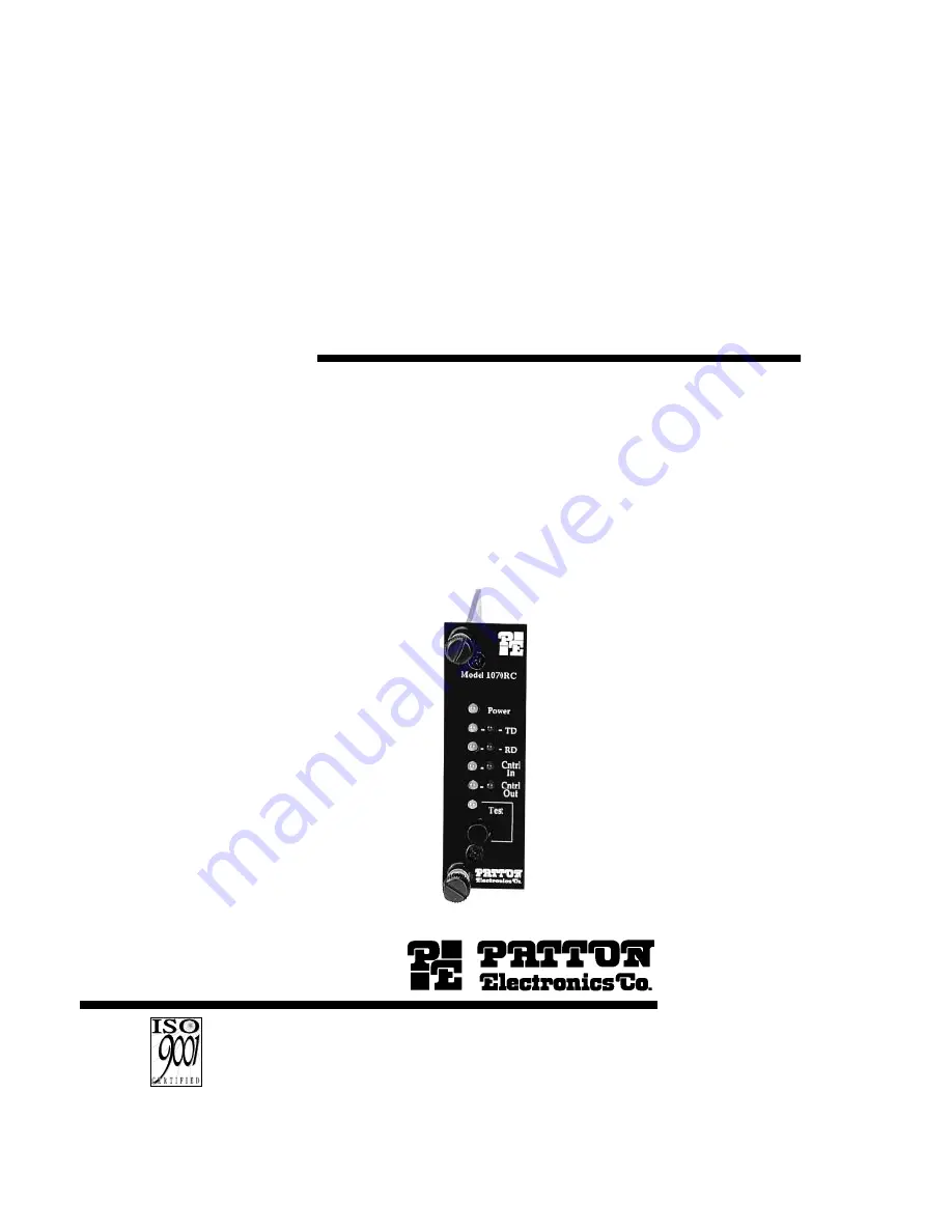
background image

USER
MANUAL

MODEL 1070RC

AC Powered, Synchronous
Short Range Modem:
Rack Mount Card

SALES OFFICE
(301) 975-1000
TECHNICAL SUPPORT
(301) 975-1007
http;//www.patton.com

Part #07M1070RC-B
Doc #067021U

, Rev. C

Revised

1/23/08

C E R T I F I E D

An ISO-9001

Certified Company

Summary of Contents for 1070RC

Page 1: ...owered Synchronous Short Range Modem Rack Mount Card SALES OFFICE 301 975 1000 TECHNICAL SUPPORT 301 975 1007 http www patton com Part 07M1070RC B Doc 067021U Rev C Revised 1 23 08 C E R T I F I E D A...

Page 2: ......

Page 3: ...ntainer This number may be obtained from Patton Electronics Technical Support 301 975 1007 http www patton com or support patton com NOTE Packages received without an RMA number will not be accepted P...

Page 4: ......

Page 5: ...configured the Model 1070RC is designed to operate transparently without need for frequent re configuration 3 1 SWITCH LOCATIONS AND ORIENTATION The eight DIP switches on the Model 1070RC board allow...

Page 6: ......

Page 7: ...ght delay in order to give the remote terminal time to receive an incoming signal Depending on the type of environment either a 0 mS 8 mS or 53 mS delay can be selected Switch 6 Switch 7 On On 0 mS On...

Page 8: ......

Page 9: ...termine various grounding characteristics for the RS 232 and twisted pair lines Figure 6 below shows the orientation of the rear interface card straps Observe that the strap can either be on pegs 1 an...

Page 10: ......

Page 11: ...d position this strap links RJ 11 pins 1 and 6 or RJ 45 pins 2 and 7 to frame ground These pins can be used as connections for the twisted pair cable shield In the open disconnected position pins 1 an...

Page 12: ......

Page 13: ...iently 4 1 1 THE RACK POWER SUPPLY The power supply included in the Model 1000R16 rack uses the same mid plane architecture as the modem cards The front card of the power supply slides in from the fro...

Page 14: ......

Page 15: ...uits such as those used with a standard Hayes type modem are not acceptable For further information about acceptable wire grades please refer to the diagrams in Appendix B 4 4 1 Point to Point Twisted...

Page 16: ......

Page 17: ...plied to the Model 1070RC front card TD RD The green TD and RD indicators blink to show positive state data activity The red TD and RD indicators blink to show negative state data activity Solid red i...

Page 18: ......

Page 19: ...1070RC All 1070RC s in the system should be tested in this manner Remote Analog Loop The Remote Analog Loop test mode causes any characters sent from the remote 1070RC to the local 1070RC to be return...

Page 20: ......

Page 21: ...e Bps Gauge AWG Distance Mi 19 22 24 19 200 2 5 2 1 1 3 9 600 3 7 2 3 1 7 4 800 4 9 4 9 2 5 2 400 8 2 5 8 4 6 1 200 10 0 8 3 6 8 To gain optimum performance from the 1070RC please keep the following g...

Page 22: ......

Page 23: ...ETTING DIRECTION EIA TIA 561 REFERENCE 8 Wire RJ 45 Contact Number Circuit Description 1 125 Ring Indicator or DSR 2 109 Received Line Signal Indicator 3 108 2 DTE Ready 4 102 Signal Common 5 104 Rece...

Page 24: ......

Page 25: ......

Page 26: ......

Page 27: ......

Page 28: ...ton com Support E mail support patton com Phone Sales 301 975 1000 Phone Support 301 975 1007 Fax 301 869 9293 Mail Patton Electronics Company 7622 Rickenbacker Drive Gaithersburg MD 20879 USA We are...

Reviews: