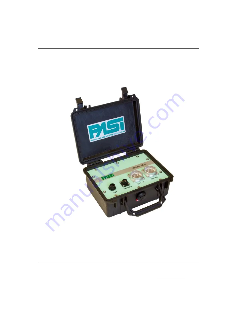
background image

PASI 


User Manual 


Seismograph GEA24 


P.A.S.I srl – via Galliari 5/E – 10125 TORINO – Italy 

Tel. +39 011 650.70.33 – Fax +39 011 658.646 - E-mail [email protected] 

www.pasisrl.it  

Summary of Contents for GEA24

Page 1: ...PASI User Manual Seismograph GEA24 P A S I srl via Galliari 5 E 10125 TORINO Italy Tel 39 011 650 70 33 Fax 39 011 658 646 E mail sales pasisrl it www pasisrl it ...

Page 2: ......

Page 3: ...stem Configuration 17 6 2 1 Configuration of linear measurement unit 17 6 2 2 Configuring geophones sensitivity unit of measure 18 6 2 3 Configuring SEG2 preferences 18 6 2 4 Configuration of the SEG2 file directory 19 6 3 Configuring acquisition parameters 19 6 3 1 Configuration window of the lines Lines configurations 20 6 3 2 Data collection configuration window Acquisition configuration 23 6 3...

Page 4: ...e 47 6 6 2 Eliminating the configuration template 48 6 7 Exporting data files only for embedded PC 48 6 8 Software upgrade only for embedded PC 48 6 9 Multiple passive acquisitions 49 6 10 Recovery after unexpected situations 50 6 10 1 Active acquisition with stacking 51 6 10 2 Continuous Passive Acquisition 52 6 10 3 Multiple passive acquisition 52 Appendix A 54 Technical Specifications 54 Append...

Page 5: ...GEA24 SEISMOGRAPH 5 Table of Contents ...

Page 6: ...re of any of its products or to discontinue the support of any of its products without any written announcement and urges its customers to ensure that the information at their disposal is valid P A S I software and programs are delivered as is The manufacturer does not grant any kind of warranty including guarantees on suitability and applicability to a certain application Under no circumstances i...

Page 7: ...GEA24 SEISMOGRAPH 7 Important Notice ...

Page 8: ...ed in this manual Faultless and safe operation of the device can be guaranteed only if the transport storage handling and operation of the device is appropriate To prevent damage use only original accessories or approved by PASI srl The box is waterproof only if closed When a suitable location has been selected for the seismograph it must be ensured that no water can get into the device under any ...

Page 9: ...GEA24 SEISMOGRAPH 9 Warranty and safety instructions ...

Page 10: ...cifications and how to use the device Please follow these guidelines Contents Chapter 5 How to use the system as regards the hardware Chapter 6 Full description of graphical interface and functionality all the features in detail offered by the system Appendix A technical characteristics of the system Appendix B how to place the piezoelectric shock sensor Appendix C Trigger connector Appendix D Con...

Page 11: ...GEA24 SEISMOGRAPH 11 Introduction ...

Page 12: ...ick Gea24 containing manual and software Registration card You can connect Gea24 to a laptop or tablet PC via USB cable the Gea24 is also powered by the PC itself so you do not need an external 12V battery The instrument is supplied with a USB key containing documents manuals and the Gea24 management software to be installed on your PC to run this simply double click on the file name Two unit Gea2...

Page 13: ...PH 13 How to use FIGURE 1 GEA24 CONNECTED TO A PC Hardware Connection Gea24 can be placed either at the ends or in the center of the spreading the patterns reported below simply represent the most common configuration ...

Page 14: ... the seismic cables to become active GEA24 must be connected to a trigger or starter geophone using the supplied special connector Power supply As indicated in Par 1 2 Gea24 is powered by the PC via the USB port an external 12V battery is not necessary ...

Page 15: ...ntation of a new acquisition button 1 paragraph 6 4 file management shown in the system key 3 paragraph 6 5 data transfer of files to an external USB drive only for embedded PC paragraph 6 7 Updating the Gea24 software only for embedded PC paragraph 6 8 These features will be described in detail in the following sections within this section you will find the following Connecting the Gea24 instrume...

Page 16: ...t to the PC must be made using the appropriate USB cable The application will automatically detect the presence of the system and will show the picture of the instrument on the GUI together with the hardware serial number If you connect two Gea24 tools there will be two images shown on the GUI with two serial numbers Tool number 1 will be the one with the lowest serial number while tool number 2 w...

Page 17: ...ate as described in paragraph 6 3 It will also be possible to change the values of the parameters and save them with a new name In the event that the operator has modified some of the template parameters without saving the file this configuration will be lost when a new change is made to the parameters or a new template is loaded If an acquisition is made the configuration will be stored and maint...

Page 18: ...or used on a single geophone to correctly interpret the voltage values measured The measurement unit is configurable at the system level so the sensitivity values of all the geophones must be inserted with the same units of measure The units of measurement used are shown in table 2 Units of measurement sensitivity of geophones V m s V cm s TABLE 2 GEOPHONES SENSITIVITY UNIT OF MEASURE 6 2 3 Config...

Page 19: ...er of the external PC the SEG2 files acquired from the system will be saved Selecting the checkbox Automatic creation of a folder for each day the system will create an additional folder within the folder you selected the name given will have the date of the day of the acquisition where all the scanned files of that day will be saved The configuration function for the SEG2 file folder is only for ...

Page 20: ...formation on a template so that the configuration can be retrieved later using the pull down menu on the homepage The operator will be asked to enter the name of the template on which to store the configuration The OK button allows you to return to the homepage and save the changes made to the default configuration template last configuration This configuration can be called back to make variation...

Page 21: ...ormed by pressing on the appropriate checkbox FIGURE 4 CONFIGURATION WINDOW OF THE LINES Via the checkbox Order inversion 1 12 the operator can reverse the order of the geophones on the line on the left by selecting the checkbox you can consider the physical geophone 1 the closest to the connector and the physical geophone 12 the furthest away from the connector Similarly you can reverse the order...

Page 22: ...tiple passive acquisition and table 4 shows the dependence of the sampling frequency for the non multiple passive acquisition Geophone ID Maximum sampling rate 7 to 12 32000 Hz 31 25us 1 to 12 16000 Hz 62 5us 13 to 24 8000 Hz 125us TABLE 3 MAXIMUM SAMPLING FREQUENCY RATE FOR ACTIVE AND PASSIVE MULTIPLE ACQUISITIONS Geophone ID Maximum sampling rate 10 to 12 2000 Hz 500us 7 to 12 1000 Hz 1ms 1 to 1...

Page 23: ...rder inversion is enabled By pressing the Acq Config we proceed to the second window of the configuration of the parameter acquisition 6 3 2 Data collection configuration window Acquisition configuration The window allows you to configure the parameters required for the acquisition The fields vary as a result of the choice made on the drop down menu Mode configuration which can be Active or Passiv...

Page 24: ...e configured or the corresponding sampling period of the signal The number of configurable values and the maximum frequency are dependent on the number and position of the geophones that have been enabled in the configuration phase of the lines as described in paragraph 6 3 1 Sampling period Sampling frequency 15 625 μs 64000 Hz 31 25 μs 32000 Hz 62 5 μs 16000 Hz 125 μs 8000 Hz 250 μs 4000 Hz ...

Page 25: ...sitivity must be configured so that it actually triggers the acquisition Trigger sensibility Very high High Medium Low Very Low TABLE 6 TRIGGER SENSITIVITY Stacking you must enter the number of stacks that you want to accomplish for the acquisition During signal visualization after acquisition it will also be possible to decide to carry out more stacking in addition to that configured in this wind...

Page 26: ...None 10 Hz 20 Hz 30Hz 40 Hz 50 Hz 70 Hz 100 Hz 150 Hz 200 Hz 300 Hz 400 Hz TABLE 7 HIGH PASS FILTER Notch filter None 50 Hz 60 Hz TABLE 8 NOTCH FILTER Low pass filer None 125 Hz 250 Hz 500 Hz 1000 Hz TABLE 9 LOW PASS FILER ...

Page 27: ...sition explanation see also page 23 Delay Time you must enter the delay in seconds from when it is manually triggered by the operator to when the geophones have to actually acquire the signal Acquisition T the time in milliseconds of duration of each acquisition made must be entered Interval you must enter the time in seconds between the start of an acquisition and the beginning of the next series...

Page 28: ...on is shown in Figure 7 FIGURE 7 NON MULTIPLE PASSIVE ACQUISITION CONFIGURATION WINDOW The following sections describe the parameters to be included in the configuration window Sampling See the active acquisition explanation see also page 23 Delay Time you must enter the delay in seconds from when the acquisition is triggered manually by the operator to when the signal acquisition by the geophones...

Page 29: ...ed template by entering the procedure storage and any changes made by the operator Figure 8 shows an example of the window FIGURE 8 CONFIGURATION VIEW WINDOW ALL GEOPHONES The example shown in figure 8 is a configuration of the lines realized by enabling the physical geophones from 1 to 6 on the left side of the first system the physical geophones from 13 to 24 on the right side of the first syste...

Page 30: ...geophone For the Gea24 system with external PC you can change the parameters directly on the table select the value with the mouse or with the tab button and enter the new value via the keyboard For the Gea24 system with embedded PC you cannot change the parameter values configured directly on the table To change the configuration values you must use an additional viewing window and change the par...

Page 31: ... of the following elements see Figure 9 geophone identifier field Id source display button SRC trigger display button TRG next geophone display button previous geophone display button keyboard for entering the numerical values of the parameters or the identifier of the geophone field display of the parameters parameter display fields X Y Z sensitivity radio buttons to select a parameter or the ide...

Page 32: ...e value regarding the geophone you want using the numeric keypad This procedure does not allow you to select the source nor the trigger The display fields will report the parameter values configured for the selected item 6 3 4 2 Changing the value of a parameter Changing the value of a parameter can be done as follows select the relevant geophone as described above press the radio button for the p...

Page 33: ...ecrease algorithms for sensitivity only the constant algorithm is available Constant value allows you to enter the constant value to be applied to the parameter Geophone 1 allows you to set the value of the first geophone for Increase and Decrease algorithms Increase allows you to set the value by which the previous parameter of the geophone will be increased to obtain the next value Decrease allo...

Page 34: ... operator has made some changes to the configuration parameter and has quit the three windows of the configuration pressing the OK button without pressing the SAVE button first in the Configuration drop down menu you will see last configuration In this case the configuration parameters are stored on a temporary file system they may be used to carry out an acquisition displayed or further modified ...

Page 35: ...eophones There are three radio buttons labelled x1 x3 and x10 that allow you to view the acquired noise at that multiplied value so low intensity signals can be displayed if thought necessary This multiplying factor has no influence on the signal acquired during the acquisition The square checkbox below the identifier of each geophone is for selecting the high gain for that geophone This high gain...

Page 36: ...stem during the gain test and modify them The window also contains the following control buttons Cancel Exits the display window of the Geophones Noise Monitoring and goes back to the homepage Acquisition Exits the noise monitoring function and moves to the acquisition start screen waiting for the trigger see section 6 4 2 1 and figure 12 or if you are creating a multiple passive acquisition on th...

Page 37: ...ows the acquisition with a pretrigger time of 500 milliseconds acquisition time after triggering of 2000 milliseconds and a system that has acquired the pretrigger data and is ready to be triggered If the event is triggered before the pretrigger time has been completed the acquisition will be correct but samples not acquired prior to the trigger event will have a value equal to zero The window als...

Page 38: ...ion the Gea24 system will carry out acquisition in a continuous way for the planned duration of the acquisition configuration whereas in the case of a multiple acquisition the Gea24 system will carry out the sequence acquisitions and pauses between acquisitions as determined by the acquisition configuration The window also contains the following command button Main Exits the acquisition window and...

Page 39: ... have been carried out To end the acquisition operation the operator can press the main button and in this case the data acquired up to that time will be deleted and the system will return to the Gea24 homepage 6 4 5 Display of acquired data After the acquisition is completed the Gea24 will proceed to collect the acquired signals and will apply any configured filters For an active acquisition the ...

Page 40: ...ready acquired file View Filters The operator can change the representation of the graphics or apply filters to the acquired signal The application of filters is only possible if no filter had been expected to be used during the acquisition configuration Stacking The operator can make further stacking acquisitions after having viewed the result of the acquisition Total this button is available aft...

Page 41: ...n the characteristics of the acquired signal The default Full allows you to view the entire signal on a single screen Amplitudes axis Number of geophones shown on a single screen this parameter consequently allows you to vary the available space for the amplitude of each signal The possible values are 24 geophones displayed 12 geophones displayed 6 geophones displayed 3 geophones displayed Amplitu...

Page 42: ...h of the maximum amplitude value measured on the single acquired signal This view will allow you to visualize in better detail the small values of amplitude of each signal but not the portions of signals whose width is greater than 1 5 of the maximum measured amplitude Show Grid Grid Presence allows you to activate or disable the presence of the reference grid on the time axis Plot Colors Selectin...

Page 43: ... the application of the filter is used only in the last display phase before saving the data The filters available are the same as in the acquisition configuration window to which reference is made for the description see section 6 3 2 2 figure 6 and are listed below High pass filter Notch Filter Suppress harmonics Low Pass Filter 6 4 7 Stacking Configuration The stacking function can also be acti...

Page 44: ...ed window 6 5 Data Backup Pressing the Save Data button on the Data acquired window it is possible to save a file in SEG2 format of the data that is displayed at that moment If digital filters have been applied during the data acquired phase the filtered data will be saved to file if the operator decides to configure the acquired signal without the application of the filters he will have to press ...

Page 45: ... 2 6 5 1 Viewing and entering SEG2 parameters After pressing the Save button the Set up Display window of the SEG2 parameters will open FIGURE 16 INPUT WINDOW OF SEG2 PARAMETERS The Configuration SEG2 Parameters window opens also when carrying out a passive acquisition immediately after the geophone noise monitoring window The window includes A drop down menu containing a list of SEG2 standard par...

Page 46: ...t appear in the table and their values are by default those used during the last saved acquisition of SEG2 file to facilitate the input of parameters in the event of repeated acquisitions Entering a new SEG2 parameter not present in the table adds that parameter to the table Entering a SEG2 parameter in the table will enable you to change the value of this parameter Pressing the Insert button the ...

Page 47: ...ns the following command button OK Exits the File Manager window and returns to the homepage 6 6 1 Viewing an SEG2 file An SEG2 file can be displayed by pressing the View Data File button This opens a management file system window of the external PC or of the embedded PC Use the directory tree to select the file of interest and press the OK button this opens a window similar to the Captured Data w...

Page 48: ...nput Output Management window after a few seconds This window also lets you update the management software as described in paragraph 5 10 The names of the files in the Gea24 control PC are shown in the display table indicating the date and time saved organized from the most recent to the oldest You can change the way they are organized by pressing the button at the top and they can be organized by...

Page 49: ... intervals In addition to configuring the parameters relative to single passive acquisition which must be done with a manual trigger acquisition time sampling frequency wait time after the trigger event the information must be configured number of repetitions number of acquisitions that have to be carried out during the multiple acquisition Repetition period in seconds the time that has to elapse ...

Page 50: ...llected in the second acquisition and saved to a SEG2 file The Gea24 program continues until it has acquired all the configured repetitions or multiple acquisition is interrupted by the operator using the specific button At the end of the multiple acquisition the Gea24 program returns to the homepage 6 10 Recovery after unexpected situations Gea24 has acquired data recovery functions when unexpect...

Page 51: ... The following shows the three possible options that the operator has 6 10 1 1 Save temporary data found on Gea24 system to an SEG2 file Data is read and recovered from the temporary files on the Gea24 system and the acquisition result is displayed on the normal acquired data window the operator can apply filters change the view discard the data without saving it or save the data to an SEG2 file w...

Page 52: ...l data can be recovered except for the acquired data of the last one or two minutes depending on sampling rate When you first turn on Gea24 system after an unexpected shutdown it will automatically save the contents of the temporary files on the system s memory this will happen on a SEG2 file with the name chosen by the operator at the start of the acquisition At the end of the recovery operation ...

Page 53: ...e global acquisition file will automatically be saved The operator will then be informed that the data has been successfully saved If the operator had not required storage of the global multiple acquisition files the Gea24 system will not have to perform any data recovery operation ...

Page 54: ...54 Appendix A Technical Specifications ...

Page 55: ...GEA24 SEISMOGRAPH 55 Appendix B Appendix B How to place the piezoelectric shock sensor ...

Page 56: ...56 Appendix C Trigger connector FIGURE 17 TRIGGER CONNECTOR ...

Page 57: ...GEA24 SEISMOGRAPH 57 Appendix D Appendix D Connection schemes 48 Channel seismograph 12 Channels cables ...

Page 58: ...58 48 Channel seismograph 24 Channels cables ...

Page 59: ...GEA24 SEISMOGRAPH 59 Appendix D Line Connections ...

Reviews: