background image

    01

290595

Ú

 Installation instructions

Gas hob 

Summary of Contents for G20

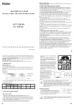
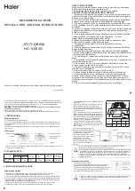
Page 1: ...01 290595 Ú Installation instructions Gas hob ...

Page 2: ......

Page 3: ...r home use only not for commercial or professional use This appliance cannot be installed on yachts or in caravans The warranty will only be valid if the appliance is used for the purpose for which it was designed After connecting the appliance check that the local conditions type of gas and pressure are compatible with the appliance settings The permissible appliance settings can be found on the ...

Page 4: ...work surface Installation of appliance Note Wear protective gloves to fit the hob Remove the pan support handles burner cap and burner heads Turn the appliance over carefully and place it on a soft cloth Make sure that the ignition parts are not damaged The adhesive seal provided prevents leaks Adhere it to the work surface around the cut out It must be adhered around the edge of the area cut out ...

Page 5: ... waste gas main All ventilation regulations must be observed Caution The gas connection must be made via a fixed i e not mobile connection gas line or via a safety hose Caution If using the safety hose ensure that the hose is not trapped or crushed The hose must not come into contact with hot surfaces Caution The gas connection must have an easily accessible locking device Safety information The n...

Page 6: ...ction If the safety earth terminal does not comply with regulations safety against electrical hazards is not guaranteed Caution You must use a H 05 W F type cable or equivalent for the appliance connection Connection for models with mains cable without plug optional Caution Appliances fitted with three core cables must be earthed Connect the wires with the mains cable according to the following co...

Page 7: ... connecting device for example a hose clamp The hose must be short and completely leak tight The hose can have a maximum length of 1 5 m Observe the current guidelines The gas hose must be replaced at least once a year Fit the flexible safety gas hose and use a screw connection or a cable clamp to tighten it securely After establishing the connection carry out a leak test See the section Leak test...

Page 8: ...burner valves must either be replaced or screwed in fully Numbers are printed on the nozzles indicating their diameter Further information about the gas types suitable for the appliance as well as the corresponding gas nozzles can be found in the section entitled Technical properties gas After the conversion After the appliance has been converted to a different gas type you must perform a leak tes...

Page 9: ...blished via a gas pipe or via a flexible safety gas hose with threaded connections at both ends Replace the gas connection pipe in the appliance with a natural gas adaptor First loosen the screw connection from the flexible safety gas hose if available or loosen the cable clamp and disconnect this from the appliance Figure 1 Remove the connecting piece held using a size 13 key from the appliance s...

Page 10: ...lade screwdriver no 2 through the drain holes ensure that you do not damage the cables and tighten the bypass nozzles as far as they will go For designs that do not have direct access to bypass nozzles optional To reach the bypass nozzles you must remove the hob See section Removing the hob After the hob has been removed remove the ignition group from the taps The bypass nozzles must then be tight...

Page 11: ...st carry out a leak test See the section Leak test Installing the hob Install in reverse order 1 Ensure that the cables are not damaged and the connections do not come loose Slowly insert the ignition group 2 Slowly place the hob onto the burners Attach the burner screws from the hob Caution In doing so ensure that ignition plug and thermal element seals do not fall under the hob 3 For versions wi...

Page 12: ...be checked using your finger or a suitable device 3 Spray the nozzle in the burner to be checked with a leakage spray 4 Push the control knob and turn it anti clockwise This supplies the nozzle with gas If small bubbles or foam form indicating a gas leak follow the instructions in the section entitled In the event of a gas leak Correct flame formation Burner The burning behaviour and soot formatio...

Page 13: ... Gas flow at 15 C and 1013 mbar g h 127 G20 G25 G30 Gas pressure mbar 20 25 29 Nozzle mm 1 15 1 28 0 85 Bypass nozzle mm 0 39 0 39 0 39 Input power max kW 3 3 3 Input power min kW 0 50 0 50 1 3 Gas flow at 15 C and 1013 mbar m h 0 286 0 333 Gas flow at 15 C and 1013 mbar g h 218 G20 G25 G30 Gas pressure mbar 20 25 29 Nozzle mm 1 03 1 04 0 68 Bypass nozzle mm 0 61 0 61 0 61 Input power max kW 3 3 3...

Page 14: ......

Page 15: ......

Page 16: ... 9001119023 9001119023 ...

Reviews: