Parker CVX0260B, Training & Maintenance Manual
The Parker CVX0260B Training & Maintenance Manual is a comprehensive guide for users looking to understand and maintain their equipment. This manual provides step-by-step instructions and troubleshooting tips to ensure optimal performance. Download the manual for free from manualshive.com and keep your equipment running smoothly.
Share
Download


Reviews:
No comments
Related manuals for CVX0260B
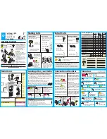
DVD-L70
Brand: Samsung Pages: 59
Orca 5010
Brand: Tait Pages: 2
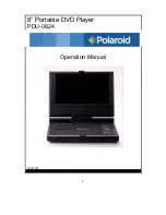
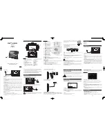
PDU-0824
Brand: Polaroid Pages: 44

SOLAR e POWER CASE 800
Brand: Wagan Pages: 19

GPS 5600A
Brand: Wacker Neuson Pages: 38

WGen3600cv
Brand: Westinghouse Pages: 79
M-335 TV
Brand: Muse Pages: 14

7471
Brand: Rally Pages: 4

GPS9700A
Brand: Wacker Neuson Pages: 200

Modular Power Series
Brand: ICT Pages: 91

30245
Brand: Troy-Bilt Pages: 28

LPM-55
Brand: CYP Pages: 16

PT3208
Brand: Kirisun Pages: 4

198693
Brand: Oras Pages: 2

JS JS-P75 JS-P75
Brand: jWIN Pages: 3

SE-8763
Brand: Pasco Scientific Pages: 18

GEN2500A
Brand: Casals Pages: 36

MSK 320B2
Brand: AA Portable Power Corp Pages: 8


