Parkeon StradaPAL, Installation Manual
The Parkeon StradaPAL, a cutting-edge parking management solution, offers an intuitive user experience. To ensure a seamless installation, our comprehensive installation manual is available for free download on our website. Simply visit manualshive.com and access the manual to effortlessly set up your StradaPAL system.
Share
Download


Reviews:
No comments
Related manuals for StradaPAL

O2
Brand: M-Audio Pages: 3

K831
Brand: Yakima Pages: 8

SD 13R07-5
Brand: FORM FIT Pages: 2

Edge Flush Rail
Brand: Thule Pages: 12

2005 Terraza
Brand: Buick Pages: 428

022 681
Brand: Atera Pages: 10

4500 CHASSIS CAB 2012
Brand: RAM Pages: 7

RMK-5
Brand: Icom Pages: 20
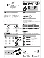
FITness band
Brand: Soul Pages: 2

2016 SLK
Brand: Mercedes-Benz Pages: 358

1500 2WD 2021
Brand: RAM Pages: 496

POLE STAR PRO
Brand: STARLANE Pages: 24

Truck 2014
Brand: RAM Pages: 330

CLS 2015
Brand: Mercedes-Benz Pages: 398

500L 2020
Brand: Fiat Pages: 284

Jumpy Miltispace
Brand: CITROËN Pages: 164

MIT4
Brand: Directed Pages: 30

1988 Riviera
Brand: Buick Pages: 161


