


PAR Everserv 600 User Manual
www.partech.com
Thank You!
Thank you for purchasing the EverServ
600. With technology specifically
designed for your environment, your
success is our passion.
1
Examine The Shipment
Please ensure all
equipment is
present.
Report any missing
or damaged equip-
ment to your PAR
Salesperson or PAR
Channel Partner.
2
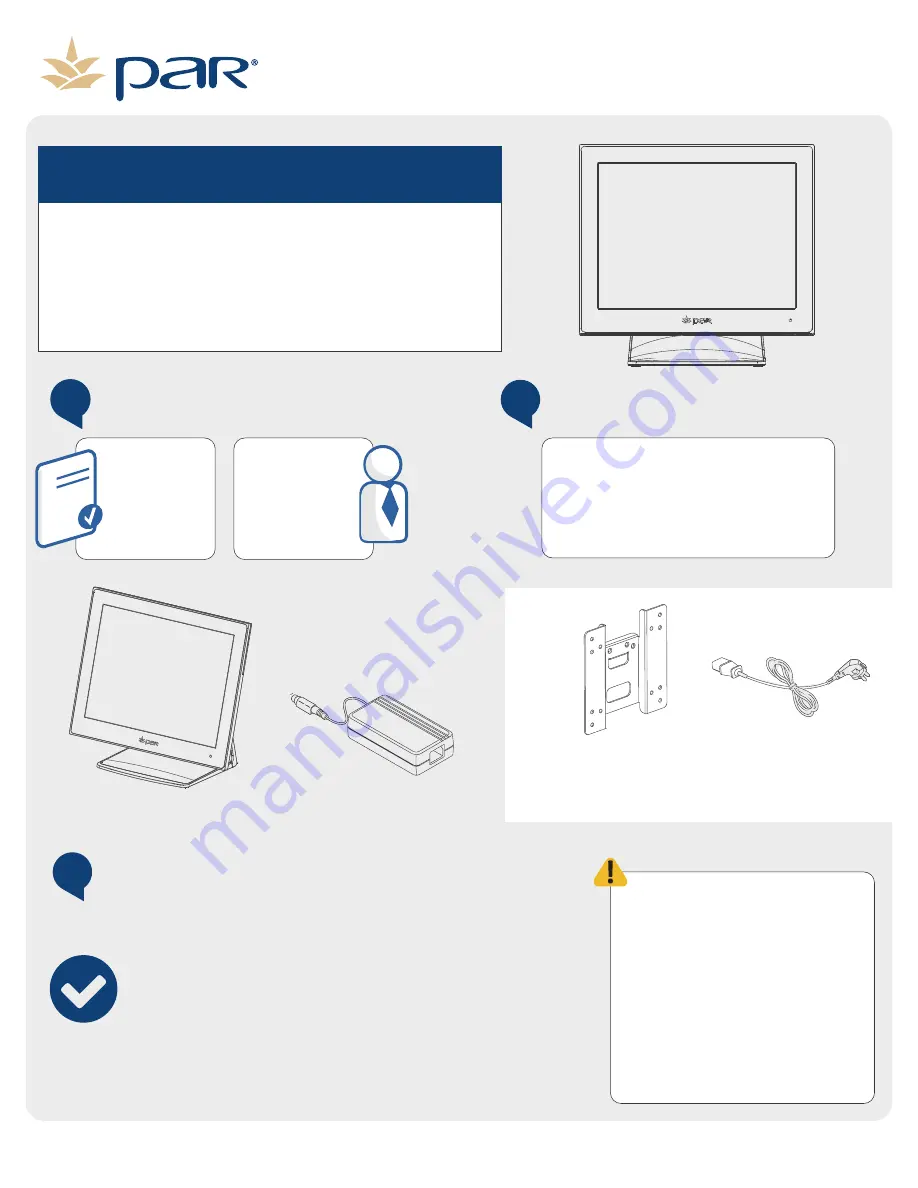
Inventory Components
3
pre-installation overview
Ensure you have the items
listed below in your order.
Power Supply
VESA Adapter Plate
(M6150-10 Model Only)
EverServ 600
Power Cord
(Packaged Seperately)
Determine what type of installa�on you will need to complete for your store.
Gather informa�on to complete the installa�on of your new system.
Inventory the equipment in your order.
Perform a backup of your current store informa�on.
Understand pre-installa�on guidelines for your store.
Before installing your new EverServ
600 system, ensure certain pre-
installa�on guidelines are followed
to protect the equipment, the store,
and the employees. If you have any
ques�ons regarding the following
guidelines, contact a PAR sales
representa�ve. If a store requires
addi�onal electrical wiring or
network cabling, you may need to
contact an electrical contractor to
perform this work.
770506502


