Panasonic WJFS616 - SWITCHER, Operating Instruction
The Panasonic WJFS616 SWITCHER is a versatile and powerful device for seamless video and audio switching. With its user-friendly interface, operating the switcher becomes effortless. To help you make the most of its features, we provide a detailed operating instruction manual for free download on our website.
Share
Download


Reviews:
No comments
Related manuals for WJFS616 - SWITCHER

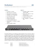
Airmux-200
Brand: Airmux Pages: 40

AM16/32B
Brand: Campbell Pages: 44

Crouse-hinds series
Brand: Eaton Pages: 6

OBID i-scan ID ISC.ANT.MUX
Brand: Feig Electronic Pages: 37

ECM8
Brand: Gamry Pages: 6

7710
Brand: Keithley Pages: 28

3761
Brand: Keithley Pages: 25

Hotwire 8774
Brand: Paradyne Pages: 19

Hotwire 8786
Brand: Paradyne Pages: 112

1195/8E1
Brand: Patton electronics Pages: 12

QK-A035
Brand: Quark-Elec Pages: 2

Seatalk QK-A033
Brand: Quark-Elec Pages: 2

1260 VXI
Brand: Racal Instruments Pages: 63

SCXI -1122
Brand: National Instruments Pages: 62

7014
Brand: Keithley Pages: 106

076P054-001
Brand: General DataComm Pages: 44

Data Multiplexer Explore 1665
Brand: Alcatel-Lucent Pages: 408
2800-101
Brand: KLIPPEL Pages: 16


