Panasonic WJ-HL208A, Operating Instructions Manual
The Panasonic WJ-HL208A is a versatile and powerful surveillance system. To unlock its full potential, make sure to download the free operating instructions manual from manualshive.com. This manual provides detailed guidance on how to maximize the product's features and functionalities, ensuring seamless operation and enhanced security.
Share
Download


Reviews:
No comments
Related manuals for WJ-HL208A

TR-71W
Brand: T&D Pages: 113

Daqstation DX1000N
Brand: YOKOGAWA Pages: 75
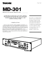
MD-301
Brand: Tascam Pages: 6

DR-M10
Brand: JVC Pages: 116

DR-M7S
Brand: JVC Pages: 116

SR-MV50US
Brand: JVC Pages: 93

DR-M10SUC
Brand: JVC Pages: 85

DR-DX5SE
Brand: JVC Pages: 92

DR-DX5SU
Brand: JVC Pages: 4

HM-DH5U
Brand: JVC Pages: 92

BD-X201MS
Brand: JVC Pages: 498

DRMV78B - DVDr/ VCR Combo
Brand: JVC Pages: 2

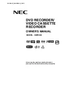
NDH-81
Brand: NEC Pages: 57
NDRV-62
Brand: NEC Pages: 61

NDR50
Brand: NEC Pages: 62

DR711
Brand: AWA Pages: 39

STronic URP Series
Brand: StealthTronic Pages: 2

33012
Brand: Enforcement Technology Group Pages: 4


