


Operating Instructions
Functional Manual
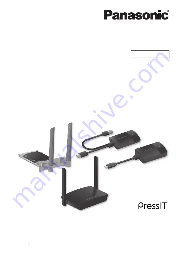
Wireless Presentation System
For business use
Model No.
TY-WPS1
TY-WPS1W
WPS Basic Set
TY-WPB1
TY-WPB1W
WPS Transmitter
TY-SB01WP
Wireless Presentation
System Receiver Board
TY-WPSC1
TY-WPSC1W
WPS USB-C Basic Set
TY-WP2BC1
TY-WP2BC1W
WPS USB-C Transmitter Set
TY-WPR1
WPS Receiver
TY-WP2B1
TY-WP2B1W
WPS Transmitter Set
TY-WPBC1
TY-WPBC1W
WPS USB-C Transmitter
*
WPS is an abbreviation of
“Wireless Presentation System”.
*
PressIT is a nickname for “Wireless Presentation System”.
English
Thank you for purchasing the Panasonic product.
•Please read these instructions before operating this product and retain them for future reference.
•
Be sure to read “Safety Precautions” (page 2 to 3) before use.
•This Operating Instructions is common to all the models regardless of suffixes of the model number.
No suffix: EU, US
W: CIS, Oceania, Hong Kong
DA0521TS3092 -PB
DPQP1383ZD/X1


