Thank you for purchasing this Panasonic product.
■
Before operating this product, please read the instructions carefully and save this manual
for future use.
■
Before using this product, be sure to read “Read this first!” (
x
pages 5 to 14).
DPQP1356ZA/X1
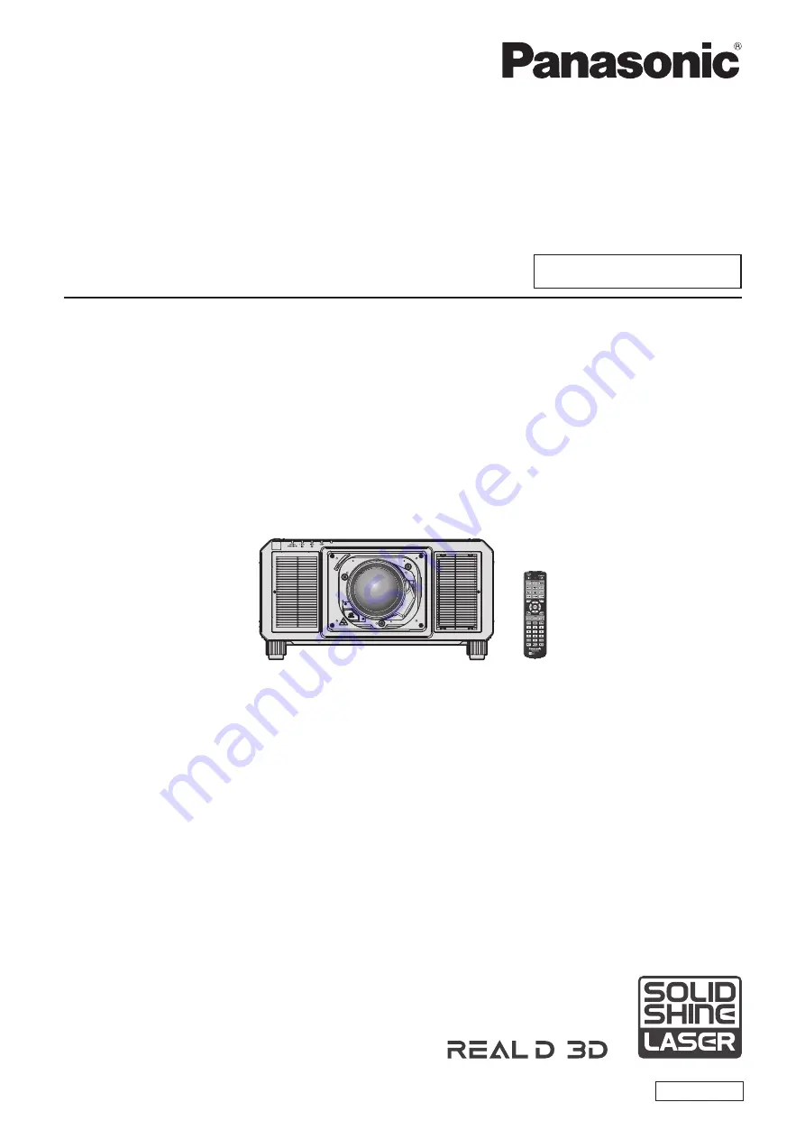
DLP™ Projector
Commercial Use
Operating Instructions
Functional Manual
ENGLISH
Model No.
PT-RZ16K
The projection lens is sold separately.