Thank you for purchasing this Panasonic product.
■
This manual is common to all the models regardless of suffixes of the Model No.
z
S: Silver model, the standard zoom lens supplied LS: Silver model, the lens sold separately
K: Black model, the standard zoom lens supplied LK: Black model, the lens sold separately
■
Before operating this product, please read the instructions carefully and save this manual
for future use.
■
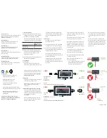
Before using your projector, be sure to read “Read this first!” (
pages 2 to 8).
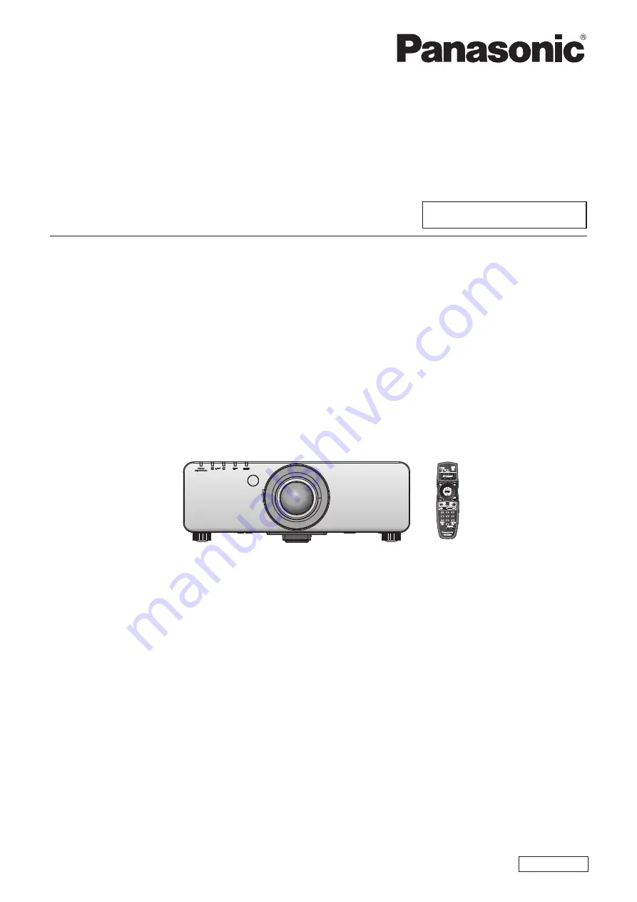
Model No.
PT-DZ770E
PT-DZ770EL
TQBJ0443-1
DLP
TM
Projector
Commercial Use
Operating Instructions
Functional Manual
ENGLISH