background image

Panasonic Corporation ©  2013.
Unauthorized copying and distribution is a violation
of law.

ORDER NO.CHM1301002CE

B35

Blu-ray Disc Player

Model No.

DMP-BDT230P
DMP-BDT230PC

Colour
(K).......................Black Type

Summary of Contents for DMP-BDT230P

Page 1: ...Panasonic Corporation 2013 Unauthorized copying and distribution is a violation of law ORDER NO CHM1301002CE B35 Blu ray Disc Player Model No DMP BDT230P DMP BDT230PC Colour K Black Type ...

Page 2: ...2 ...

Page 3: ...3 ...

Page 4: ...t when the Disc cannot be ejected by OPEN CLOSE button 17 7 Service Mode 18 7 1 Self Diagnosis and Special Mode Setting 18 8 Service Fixture Tools 30 9 Disassembly and Assembly Instructions 31 9 1 Unit 31 9 2 BD Drive 34 9 3 Disassembly from the traverse unit assembly of the optical pick up unit and precautions on ESD preventive 38 9 4 Adjustment of BD Drive 42 10 Measurements and Adjustments 44 1...

Page 5: ...tal does not have a return path to the chassis the reading must be 1 1 2 Leakage current hot check See Figure 1 1 Plug the AC cord directly into the AC outlet Do not use an isolation transformer for this check 2 Connect a 1 5kΩ 10 watts resistor in parallel with a 0 15μF capacitors between each exposed metallic part on the set and a good earth ground such as a water pipe as shown in Figure 1 3 Use...

Page 6: ...6 1 2 1 Micro Fuse conducting check This unit uses the Micro Fuse Check the Micro Fuse conducting using the Tester at the check points below ...

Page 7: ...of the assembly 3 Use only a grounded tip soldering iron to solder or unsolder ES devices 4 Use only an anti static solder removal device Some solder removal devices not classified as anti static ESD protected can generate electrical charge sufficient to damage ES devices 5 Do not use freon propelled chemicals These can generate electrical charges sufficient to damage ES devices 6 Do not remove a ...

Page 8: ...8 2 2 Precaution of Laser Diode ...

Page 9: ...s used Definition The letter of PbF is printed on the PCB using the lead free solder To put lead free solder it should be well molten and mixed with the original lead free solder Remove the remaining lead free solder on the PCB cleanly for soldering of the new IC Since the melting point of the lead free solder is higher than that of the normal lead solder it takes the longer time to melt the lead ...

Page 10: ...e control simultaneously for operations such as initialization or service mode etc 3 2 Entering Special Modes with Combination of Multiple Pressing on the Remote Control Enter the following special modes by multiple pressing functions on the supplied remote control After entering each mode switch to the desired menus for operation ...

Page 11: ...indow 3 2 2 Nondisclosure mode 1 Combination of multiple pressing 6 7 Yellow Press and hold 6 7 Yellow on the remote control simultaneously for about 5 sec then 50 RET is displayed on FL display window 3 2 3 Nondisclosure mode 2 Combination of multiple pressing 5 9 Red Press and hold 5 9 Red on the remote control simultaneously for about 5 sec then 70 RET is displayed on FL display window ...

Page 12: ...SB device which is stored pre downloaded firmware update file 3 3 2 1 Updating firmware via the internet Occasionally Panasonic may release updated firmware for this unit that may add or improve the way a feature operates These updates are available free of charge This unit is capable of checking the firmware automatically when connected to the Internet via a broadband connection When a new firmwa...

Page 13: ...der of the USB device If using CD R instead of USB device burn the file to a blank CD R by writing software 3 Update the unit 1 Turn the unit power on 2 After the home screen is displayed and HOME is displayed at LED display of front panel insert the USB device stored downloaded latest firmware file to front USB port of the unit or set the CD R into the unit and playback it 3 UPDATE is displayed a...

Page 14: ...mat 1 DVD Video DVD Video format CD Audio CD DA CD R CD RW CD DA JPEG 2 MPO 2 MP3 2 MKV 2 5 WAV 2 FLAC 2 AAC 2 WMA 2 1 Finalizing is necessary 2 ISO9660 level1 or 2 except for extended formats Joliet This unit is compatible with multi session This unit is not compatible with packet writing 3 UDF1 02 without ISO9660 UDF1 5 with ISO9660 4 UDF2 5 5 MPEG 4 ASP Level 4 MPEG2 Video AAC LC MP3 Dolby Digi...

Page 15: ... BD Region A Dimensions 430mm W Approx 16 15 16 W 38mm H Approx 1 1 2 H 179mm D Approx 7 1 16 D Mass Approx 1 4 kg 3 08 lbs Solder This model uses lead free solder PbF Note Specifications are subject to change without notice ...

Page 16: ...16 5 Location of Controls and Components ...

Page 17: ...ay 2 Repeatedly press on the remote control or POWER on the unit until 06 FTO is displayed on the unit s display 3 Press OK on the remote control or OPEN CLOSE on the unit 6 1 2 When the Forcible Disc Eject can not be done 1 Turn off the power and pull out AC cord 2 Put deck so that bottom can be seen 3 Insert the Paper clip etc into the hole on the bottom of BD Drive and slide the Paper clips etc...

Page 18: ...appears only when the connection is released Neither the button operation nor the passage of the fixed time disappear the display No display U72 display disappears when error has been solved by Power OFF ON of connecting equipment or by inserting removing of HDMI cable U73 HDMI connection error authentication error When authentication error occurs while the equipments TV amplifier etc are connecte...

Page 19: ...dication flows sideways NO READ Disc read error A disc is flawed or dirty A poor quality failed to start The track information could not be read Cannot read Please check the disc HARD ERR Drive error The drive detected a hard error BD Drive error It is display for 5 seconds The character indication flows sideways SELF CHECK Restoration operation Since the power cord fell out during a power failure...

Page 20: ...g Persistent Storage of BD ROM standard is cleaned While the unit is on press and hold 6 7 and Y on the remote control at the same time for more than 5 seconds 50 RET is displayed on the unit s disply Repeatedly press on the remote control or POWER on the unit until 51 NOP is displayed on the unit s display Press and hold STOP on the remote control until 52 BRE is displayed on the unit s display P...

Page 21: ...9 and R on the remote control at the same time for more than 5 seonds 70 RET is displayed on the unit s display Repeatedly press on the remote control or POWER on the unit until 81 AIG is displayed on the unit s display Press OK on the remote control or OPEN CLOSE on the unit for at least 3 seconds Item FL display Key operation Mode name Description ...

Page 22: ...ote control until 10 OCL is displayed on the unit s display Press OK on the remote con trol or OPEN CLOSE on the unit When press OPEN CLOSE key while the tray being locked Display LOC on the screen Press OPEN CLOSE key while the tray is being locked Progressive initialization The progressive setting is initialized to Interlace While the unit is on press and hold OK B and Y on the remote control at...

Page 23: ...mmand is as follows NOTE Do not use it excluding the designated command Item FL display Key operation Mode name Description Remote controller key Release Items Item of Service Mode executing is cancelled Press 0 0 or Return in service mode Error Code Display Last Error Code of U F held by Timer is dis played on FL Details are described in 7 1 1 Self Diagnosis Functions If any error history does no...

Page 24: ...ser used time BD Playback Laser used time DVD Playback Laser used time CD Playing is the used time display in hour Laser used time of BD DVD CD in Playback mode is counted Press 4 1 in service mode Item FL display Key operation Mode name Description Remote controller key ...

Page 25: ...econds YY Year MM Month DD Date 3 Last drive error 1 2 is displayed for 5 seconds 00 Bad disc 03 Bad disc 04 Bad disc or drive malfunction 4 Last drive error 2 2 is displayed for five seconds 5 Error occurring disc type is dis played for 5 seconds Press 4 2 in service mode Item FL display Key operation Mode name Description Remote controller key ...

Page 26: ...26 6 Disc maker ID is displayed for 5 seconds In case that the maker cannot be identified display is blackout Item FL display Key operation Mode name Description Remote controller key ...

Page 27: ...ze FE 0 99999 FE symmetry 0 99999 Number of reflection surface 0 2 Measurements failure 1 Insert the Panasonic BD VIDEO SL Disc Ver 1 0 Ver 2 0 into the tray Incompatible with other media 2 Press 4 8 CEC H Output The CEC terminal high output of HDMI Press 5 5 in service mode Item FL display Key operation Mode name Description Remote controller key ...

Page 28: ...a remote control Input the 6 digits adjust value that is in the Drive or OPU replacement part with the remote control s num ber keys in the service mode When register successful When register fail Press 7 2 in service mode Tray OPEN CLOSE Test The BD Drive tray is opened and closed repeatedly is number of open close cycle times Press 9 1 in service mode When releasing this mode pull out AC cord De...

Page 29: ...rvice mode Initialization of the Service Mode Last Drive Error Error History and Error code information stored on the unit are initialized to factory setting Press 9 9 in service mode Release Service Mode Release Service Mode and turns the Power Off Display in STOP SS mode Press POWER button on the front panel or Remote controller in ser vice mode Item FL display Key operation Mode name Descriptio...

Page 30: ...KZ0327 Extension Cable Digital P C B Power P C B 15 Pin 1 Same as BDT220 Series RFKZ03D01KS Lead Free Solder 0 3mm 100g Reel Same as BDT220 Series RFKZ06D01KS Lead Free Solder 0 6mm 100g Reel Same as BDT220 Series RFKZ10D01KS Lead Free Solder 1 0mm 100g Reel Same as BDT220 Series RFKZ0316 Solder Remover Lead free low temperature Solder 50g Same as BDT220 Series RFKZ0328 Flux Same as BDT220 Series ...

Page 31: ...9 1 1 Disassembly Flow Chart The following chart is the procedure for disassembling the casing and inside parts for internal inspection when carrying out the servicing To assemble the unit reverse the steps shown in the chart below 9 1 2 P C B Positions ...

Page 32: ...he hole on the bottom of BD Drive and slide the Paper clips etc in the direction of the arrow to eject tray slightly 3 Remove the tray top from the tray section 9 1 4 2 Front Panel 1 Unlock 7 tabs A G turn Pull with the Front Panel in the direction of your side 9 1 5 WiFi Module 1 Remove the connector 2 Remove the WiFi Module from the Spacer Note when replacing the front panel ass y the rubber pas...

Page 33: ...ode from the ESD damage 2 Remove the 3 FFCs 3 Remove the 2 Screws A remove 2 tabs B of BD Drive in the direction of the arrow to remove BD Drive 9 1 8 Rear Panel 1 Remove the 2 Screws A and Screw B 2 Unlock 2 locking Tabs C to remove the Rear Panel 9 1 9 Power P C B 1 Remove the connector A 2 Remove the 2 Screws B 9 1 10 Digital P C B 1 Remove the 2 Screws A to remove Digital P C B ...

Page 34: ... front of the mecha chassis to both sides of the drive to unlock the tray and push it outward simultaneously Notes when attaching the tray 1 Push Slide cam to the left side slightly and make sure the tray band is between the two posts of Slide cam when attaching the tray 9 2 2 Pulley Gear Belt 1 Perform the step Tray 2 Push the Post to the direction of arrow by using the slotted screwdriver 3 Remo...

Page 35: ...m the mecha chassis 3 Pull the hooks at both sides to remove the side post on the mid base 4 Slide the Slid cam in the direction as shown and then take the front post out of the slide cam track 5 Take the damper out of the mecha chassis and remove the Drive ass y 6 Remove the Slide Cam ...

Page 36: ...36 9 2 4 Drive Gear and Loading Motor 1 Perform the step Slide Cam 2 Remove the Drive Gear 3 Loosen the hooks and remove the Loading Motor Unit and the SW Ass y ...

Page 37: ...37 9 2 5 Grease ...

Page 38: ...ase apply an ESD prevention bag RPFC0114 to the OPU FFC and weld the short circuit solder a Set the temperature of iron is 350 C b When using the iron head do not apply a force more than 1N to the pad Do not touch any other compo nents around the welding spot c Welding should be applied less than 3 seconds 2 Remove the connector and take out the OPU FFC 3 Remove the Mid base ...

Page 39: ...t the shaft into the shaft hole of the base install the OPU to the auxiliary shaft and then attach the nut piece unit onto the screw stem 2 Assembly of spring a Insert the two springs to the ends of the shaft b Then insert the handle B of the spring into the spring holder as shown in Figure c Press down the handle A of the spring as shown in Figure into the hole 3 Apply the lubricants to the 1 poi...

Page 40: ...as shown in Fig remove the solder in the direction as shown b Set the temperature of iron below 350 C c When using the iron head do not apply a force more than 1N to the pad Do not touch any other compo nents around the welding spot d Welding should be applied less than 3 seconds ...

Page 41: ...41 9 3 3 How to Clean the Lens of Optical Pick UP ...

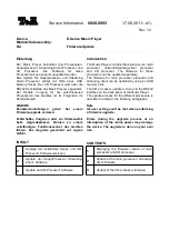
Page 42: ...42 9 4 Adjustment of BD Drive 9 4 1 Repair Flowchart ...

Page 43: ...gistration status will display on the TV When register successful DQR_OK When register fail DQR_NG 4 Release command Press the numeral keys 0 0 to end the input mode 9 4 2 2 The reading method of Engineering Adjusted Value 1 Input 0 9 with the remote control s numeral keys in the service mode The TV display 6 digits of Engineering Adjusted Value at this time Please noted it on paper 2 Reading Engi...

Page 44: ...44 10 Measurements and Adjustments 10 1 Service Positions NOTE For description of the disassembling procedure see the section 9 10 1 1 Checking and Repairing of Power P C B ...

Page 45: ...45 10 1 2 Checking and Repairing of BD Drive and Digital P C B ...

Page 46: ...isc No abnormality should be seen in the picture sound or operation 5 If a problem is caused by a BD Video disc VCD DVD R DVD Video Audio CD or MP3 playback the test disc No abnormality should be seen in the picture sound or operation 6 After checking and making repairs upgrade the firmware to the latest version Make sure that FIN appears in the FL displays NoUPd display means the unit is already ...

Page 47: ...LER OVERALL BLOCK DIAGRAM KEY USB PORT P6804 FL BUZZER IC53003 LASER DIODE MOTOR DRIVE FOCUS COIL BEAM EXPANDER TRACKING COIL TRAVERSE MOTOR SPINDLE MOTOR LOADING MOTOR SD CARD P6802 T59401 PHYSICAL LAYER TRAVERSE DIGITAL AUDIO OUT OPTIAL P59001 IC51301 ETHER NET PORT NAND FLASH ROM 1GB REMOTE SENSOR HDMI JK56301 TERMINAL T U O V A SDRAM 1GB IC52001 IC52002 IC52201 DMP BDT230P PC ...

Page 48: ...SURGE SUPPRESSOR AND SURGE ABSOBER D1006 C1014 RECTIFIER T1001 POWER TRANSFORMER IC1021 SWITCHING IC FB OLF VCC Q1022 FEED BACK D1110 ERROR VOLTAGE DET TO DIGITAL P C B PW_X_SW12 2V 10 P58001 P1102 13 14 15 P58001 P1102 PW_X_SW5 1V HOT COLD MAIN P C B POWER BLOCK DIAGRAM D1022 6 7 8 DMP BDT230P PC IC1103 R A K D1111 ...

Page 49: ...T 4 IC56301 18 8 PW_STANBY_3 3V REG 3 3V IC58100 Q58120 CE VDD 4 1 VOUT 3 IC59001 IC51001 AVDD33 DVCC33 3 PW_USB_5 1V_F1 REG 5 1V IC58500 VI EN 3 1 VO 6 FLG 4 P59001 18 IC51001 E1 FROM Ether_USB_SD SECTION IC51001 E2 USB_F1_EN USB_F1_OC PW_USB_5 1V_W REG 5 1V IC58520 VI EN 3 1 VO 6 FLG 4 P59301 4 IC51001 H2 FROM Ether_USB_SD SECTION IC51001 G1 USB_W_EN USB_W_OC REG 3 3V IC58111 CE 1 VOUT 4 PW_DR5V...

Page 50: ... P9 P10 P11 P12 P13 P14 P15 P16 6G 5G 4G 3G 2G 1G SG14 14 16 17 18 19 20 10 11 12 13 14 15 21 22 23 24 9 27 SG15 28 SG16 29 GR6 GR1 37 42 3 4 5 6 7 8 DIN CLK STB IC7001 DISPLAY LED DRIVE SMPIO10 FL_DCDC_ON_H G_FL_TXD G_FL_CK VSTB G_FL_CS VEE P1102 P58001 6 9 8 7 DOUT 6 30 VDD 13 VDD 43 26 25 1 2 P1102 P58001 8 P1102 P58001 5 P1102 P58001 7 PW 21V VP PW 15V PW 18V F F 5 3 4 1 8 9 QR1170 Q1170 D1173...

Page 51: ...SLED2 SLED2 FCS LOAD STP1 BEMF detector Digital core pre driver power FET SLED END detection STEP END detection DAC PWM DAC PWM DAC PWM DAC PWM DAC PWM DAC PWM DAC PWM DAC SLD_ENA TLT_ENA TRK_ENA STP_ENA power monitor LOAD_ENA F B F B F B F B F B SLD_ENA pre driver power FET pre driver power FET pre driver power FET pre driver power FET pre driver power FET pre driver power FET pre driver power FE...

Page 52: ...GND SW3 GND GND1 LDI_BD LDI_DVD NC GND GND NC GND NC MON SEL_CD SEL_DVD VREF_PD SEL_BD VCC_ 5PD FCS1 TRK FCS2 TRK FCS2 NC NC B A B A FCS1 B A A B B A A B P55004 2 1 3 4 5 2 1 3 4 5 V U W COM GND V U W COM GND P55005 2 1 3 4 5 2 1 3 4 5 GND CLOSESW LDM OPENSW LDM GND CLOSESW LDM OPENSW LDM KEY4 Power PW_X_SW12R2V FL_CS FL_CK KEY1 EJECT KEY3 PLAY KEY2 STOP PW_X_SW3R3V FL_TXD FL_DC_DC_ON_H GND PW_X_S...

Page 53: ...OTE Circuit waveform described herein shall be regarded as reference information when probing defect point because it may differ from an actual measuring value due to difference of Measuring instrument and its measuring condition and product itself 13 1 1 Waveform Chart ...

Page 54: ...Model No DMP BDT230P DMP BDT230PC SCHEMATIC DIAGRAM NOTICE ...

Page 55: ...Model No DMP BDT230P DMP BDT230PC PART LIST NOTICE ...

Page 56: ...Model No DMP BDT230P DMP BDT230PC ABBREVIATIOM ...

Page 57: ...Model No DMP BDT230P DMP BDT230PC POWER SECTION POWER P C B ...

Page 58: ...Model No DMP BDT230P DMP BDT230PC FL SECTION POWER P C B ...

Page 59: ...Model No DMP BDT230P DMP BDT230PC SD_USB SECTION SD_USB P C B ...

Page 60: ...Model No DMP BDT230P DMP BDT230PC AUDIO DAC SECTION DIGITAL P C B ...

Page 61: ...Model No DMP BDT230P DMP BDT230PC ETHER USB SD SECTION DIGITAL P C B ...

Page 62: ...Model No DMP BDT230P DMP BDT230PC DIGITAL NET SECTION DIGITAL P C B ...

Page 63: ...Model No DMP BDT230P DMP BDT230PC DDR3 CH A SECTION DIGITAL P C B ...

Page 64: ...Model No DMP BDT230P DMP BDT230PC DDR3 CH B SECTION DIGITAL P C B ...

Page 65: ...Model No DMP BDT230P DMP BDT230PC FLASH IR VFD SECTION DIGITAL P C B ...

Page 66: ...Model No DMP BDT230P DMP BDT230PC HDMI AV SECTION DIGITAL P C B ...

Page 67: ...Model No DMP BDT230P DMP BDT230PC HDMI SUB SECTION DIGITAL P C B ...

Page 68: ...Model No DMP BDT230P DMP BDT230PC FE SECTION DIGITAL P C B ...

Page 69: ...Model No DMP BDT230P DMP BDT230PC POWER P C B COMPONENT SIDE ...

Page 70: ...Model No DMP BDT230P DMP BDT230PC POWER P C B FOIL SIDE ...

Page 71: ...Model No DMP BDT230P DMP BDT230PC SD_USB P C B COMPONENT SIDE ...

Page 72: ...Model No DMP BDT230P DMP BDT230PC SD_USB P C B FOIL SIDE ...

Page 73: ...Model No DMP BDT230P DMP BDT230PC DIGITAL P C B COMPONENT SIDE ...

Page 74: ...Model No DMP BDT230P DMP BDT230PC DIGITAL P C B FOIL SIDE ...

Page 75: ...03600036 DIODE 1 E S D D1025 B0BA01700055 DIODE 1 E S D D1031 B0EAKV000090 DIODE 1 E S D D1110 B0JCNG000011 DIODE 1 E S D D1111 B0JARG000017 DIODE 1 E S D D1171 B0BA02100037 DIODE 1 E S D D1172 B0BA03600036 DIODE 1 E S D D1173 B0HAMM000106 DIODE 1 E S D D1175 B0BA01700058 DIODE 1 E S D D1176 B0JAMF000008 DIODE 1 E S D F1001 K5G202Y00006 FUSE 1 IC1021 C0DACYY00011 IC 1 E S D IC1103 C0DBZYY00486 IC ...

Page 76: ...1H200A557 50V 20P 1 C51010 F1G1A1040006 10V 0 1U 1 C51011 F1L0G107A002 6 3V 100U 1 C51012 F1G1A1040006 10V 0 1U 1 C51014 F1G1A1040006 10V 0 1U 1 C51015 F1G1A1040006 10V 0 1U 1 C51016 F1G1A1040006 10V 0 1U 1 C51017 F1G1A1040006 10V 0 1U 1 C51018 F1G1A1040006 10V 0 1U 1 C51019 F1G1A1040006 10V 0 1U 1 C51020 F1G1A1040006 10V 0 1U 1 C51021 F1G1A1040006 10V 0 1U 1 C51022 F1G1H101A541 50V 100P 1 C51023 ...

Page 77: ... C52118 F1G1H101A565 50V 100P 1 C52119 F1G1H101A565 50V 100P 1 C52151 F1G1A1040006 10V 0 1U 1 C52152 F1G1A1040006 10V 0 1U 1 C52153 F1G1A1040006 10V 0 1U 1 C52154 F1G1A1040006 10V 0 1U 1 C52155 F1G1A1040006 10V 0 1U 1 C52156 F1G1A1040006 10V 0 1U 1 C52157 F1G1A1040006 10V 0 1U 1 C52158 F1G1A1040006 10V 0 1U 1 C52159 F1G1A1040006 10V 0 1U 1 C52160 F1G1A1040006 10V 0 1U 1 C52161 F1G1A1040006 10V 0 1...

Page 78: ... 1 C55068 F1G1A1040006 10V 0 1U 1 C55076 F1G1C104A077 16V 0 1U 1 C55077 F1G1C104A077 16V 0 1U 1 C55079 F1G1A1040006 10V 0 1U 1 C55080 F1H0J2250008 6 3V 2 2U 1 C55081 F1H0J2250008 6 3V 2 2U 1 C55082 F1G1E1030005 25V 0 01U 1 C55083 F1G1E1030005 25V 0 01U 1 C55085 F1K1E1060001 25V 10U 1 C55086 F1G1E1040001 25V 0 1U 1 C55087 F1J1A106A043 10V 10U 1 C55088 F1G1E1040001 25V 0 1U 1 C55093 F1G1E102A086 25V...

Page 79: ...014 6 3V 10U 1 C58600 F1H1A105A028 10V 1U 1 C58601 F1H1A105A028 10V 1U 1 C59001 F1G1A1040006 10V 0 1U 1 C59002 F1G1A1040006 10V 0 1U 1 C59003 F1G1A1040006 10V 0 1U 1 C59004 F1G1A1040006 10V 0 1U 1 C59005 F1G1A1040006 10V 0 1U 1 C59006 F1G1A1040006 10V 0 1U 1 C59007 F1G1A1040006 10V 0 1U 1 C59008 F1G1A1040006 10V 0 1U 1 C59401 F1G1A1040006 10V 0 1U 1 C59402 F1G1A1040006 10V 0 1U 1 FL59601 J0MAB0000...

Page 80: ...41 TRANSISTOR 1 E S D R51001 D0GA105JA023 1 16W 1000K 1 R51002 D0GAR00J0005 1 16W 0 1 R51005 D0GA103JA023 1 16W 10K 1 R51006 D0GA103JA023 1 16W 10K 1 R51007 D0GA103JA023 1 16W 10K 1 R51008 D0GA101JA023 1 16W 100 1 R51009 D0GA103JA023 1 16W 10K 1 R51010 D0GA101JA023 1 16W 100 1 R51011 D0GA103JA023 1 16W 10K 1 R51012 D0GA472JA023 1 16W 4 7K 1 R51013 D0GA101JA023 1 16W 100 1 R51016 D0GA101JA023 1 16W...

Page 81: ...1 16W 10K 1 R58401 ERJ2RHD472X 1 16W 4 7K 1 R58402 ERJ2RHD273X 1 16W 27K 1 R58500 ERJ2RHD152X 1 16W 1 5K 1 R58501 ERJ2RHD183X 1 16W 18K 1 R58502 D0GA474JA023 1 16W 470K 1 R58520 ERJ2RHD333X 1 16W 33K 1 R58522 D0GA474JA023 1 16W 470K 1 R59001 ERJ2RHD512X 1 16W 5 1K 1 R59002 ERJ2RHD512X 1 16W 5 1K 1 R59003 ERJ2RHD243X 1 16W 24K 1 R59102 D0GA103JA023 1 16W 10K 1 R59201 D0GA103JA023 1 16W 10K 1 R59202...

Page 82: ...2 F1H1H102A219 50V 1000P 1 C6804 F1J0J226A014 6 3V 22U 1 C7701 F1H1A105A028 10V 1U 1 IR7001 PNJ4881M02VT REMOTE SENSOR 1 R7701 ERJ3GEYJ330V 1 10W 33 1 R6801 D0GF1R0JA049 1 2W 1 1 R6802 D0GF1R0JA049 1 2W 1 1 R6803 ERJ3GEYJ820V 1 10W 82 1 R6804 ERJ3GEYJ820V 1 10W 82 1 R6805 ERJ3GEYJ820V 1 10W 82 1 R6806 ERJ3GEYJ330V 1 10W 33 1 R6807 ERJ3GEYJ820V 1 10W 82 1 R6808 ERJ3GEYJ820V 1 10W 82 1 R6809 ERJ3GEY...

Page 83: ...Model No DMP BDT230P DMP BDT230PC Exploded View ...

Page 84: ...Model No DMP BDT230P DMP BDT230PC Mechanism View ...

Page 85: ...Model No DMP BDT230P DMP BDT230PC Packing View ...

Page 86: ... 33 RHD30168 J SCREW 1 34 RHD30168 J SCREW 1 35 RHD30168 J SCREW 1 36 RHD30168 J SCREW 1 37 RHD30168 J SCREW 1 38 RHD30168 J SCREW 1 39 XSN3 4FJ SCREW 1 46 RHD30119 U SCREW 1 47 RHD30119 U SCREW 1 48 RHD30119 U SCREW 1 49 RHD30119 U SCREW 1 50 RHD30119 U SCREW 1 101 VQL2P54 LASER CAUTION LABEL 1 102 VMA0V86 YOKE 1 103 VMD6392 J CLAMPER 1 104 VMD6881 TRAY 1 105 VMD6580 MID BASE 1 106 VDG1756 1J PUL...

Page 87: ...22 AC CORD 1 A4 N2QAYB000874 REMOTE CONTROL UNIT 1 A6 RPFC0119 1 POLYETHYLENE BAG 1 A7 VQT4V26 OPERATING INSTRUCTIONS 1 IA A7 VQT4V27 OPERATING INSTRUCTIONS 1 IB BDT230PC A11 RQCS0634 CANADIAN FRENCH SHEET 1 BDT230PC PACKING PC1 RYQ1206 Z PACKING CASE 1 BDT230P PC1 RYQ1207 Z PACKING CASE 1 BDT230PC PC2 RPF0662 POLYETHYLENE BAG 1 PC3 RPN2571A CUSHION A 1 PC4 RPN2571B CUSHION B 1 ...

Reviews: