Panasonic AG-DVC 200E, Operating Instructions Manual
The Panasonic AG-DVC 200E is a professional-grade camcorder that captures stunning high-definition footage. To ensure ease of use, it comes with an Operating Instructions Manual that guides users through its features and settings. You can download this essential manual for free from manualshive.com, enabling you to make the most of your Panasonic AG-DVC 200E.
Share
Download


Reviews:
No comments
Related manuals for AG-DVC 200E
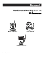
IPCAM-WO
Brand: Honeywell Pages: 10

iPCAM-WL
Brand: Honeywell Pages: 2
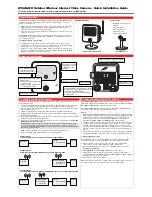
IPCAM-WO
Brand: Honeywell Pages: 2

CC2700
Brand: AgfaPhoto Pages: 68

CG1000
Brand: RECORDER GEAR Pages: 16

XCL-S600
Brand: Sony Pages: 4

8 VP-L600
Brand: Samsung Pages: 67

HC-V550P
Brand: Panasonic Pages: 36

MV5iMC
Brand: Canon Pages: 181

SC-D590
Brand: Samsung Pages: 109
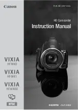
VIXIA HFM41
Brand: Canon Pages: 204

HDTV/FX Filter
Brand: Tiffen Pages: 1

HC-V700P
Brand: Panasonic Pages: 81

Everio GZ-MG130
Brand: JVC Pages: 2

EVERIO GZ-HM440US
Brand: JVC Pages: 2

D8 Digital Handycam DCR-TRV720E
Brand: Sony Pages: 212

D8 Digital Handycam DCR-TRV820E
Brand: Sony Pages: 233

D8 Digital Handycam DCR-TRV420E
Brand: Sony Pages: 287


