Quick Installation Guide
Version 1.0
Q
uick
I
nstallation
G
uide
PRINTED ON RECYCLED PAPER
Q I G
1907-2-29-IAPW42X-1.0
Installation
The device can be fixed to a pole or the wall using the
supplied
mounting
kits.
Before
installing
the device,
make
sure
you
have
all
of
the
package
contents
available
and
a
PC
with
Microsoft
Internet
Explorer 6.0
or
later,
for
using
web-based
system
management
tools.
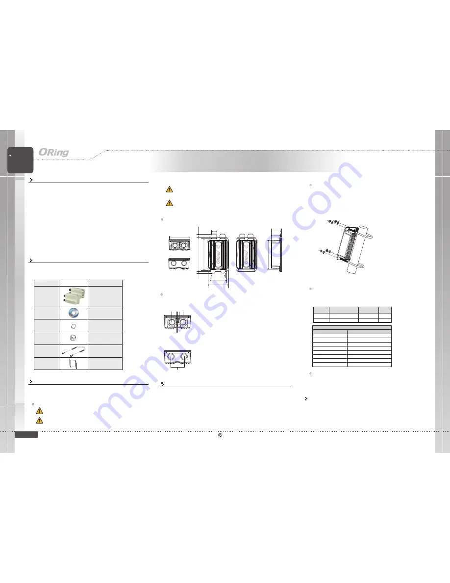
Dimension
Panel
Layouts
Front Panel
1. Non-PoE LAN port
2. PoE LAN port
3. LNK/ACT LED for non-PoE LAN port
4. LNK/ACT LED for PoE LAN port
5. WiFi connections (weakest signal strength at
the bottom, strongest at the top)
6. Power indicator
7. Reset button
Network Connection
The
device
has
two 10/100Base-T(X) Ethernet
ports.
According
to
the
link
type,
the
AP
uses
CAT 3, 4, 5, 5e, 6UTP
cables
to
connect
to
any
other
network
device (PCs,
servers,
switches,
routers,
or
hubs).
Cable
Type
Max. Length
Connector
10Base-T
Cat. 3, 4, 5 100-ohm
UTP 100 m (328 ft)
RJ45
100Base-TX
Cat. 5 100-ohm UTP
UTP 100 m (328 ft)
RJ45
IAP-W420+/W422+
Introduction
The
IAP-W420+/W422+
is a reliable IP-67 outdoor IEEE 802.11 b/g/n
WLAN
access
point
with
two
10/100Base-T(X) P.D. Ethernet ports. It can be
configured to operate in AP/Client/AP-Client/Bridge modes and is specifically
designed for the toughest industrial environments. The combination of an IP-
67 design and superb management functionality, the
IAP-W420+/W422+
provides a waterproof, dust-tight connection. In addition,
IAP-W420+
provides a high power output of 800mw and throughput up to 80Mbps to
satisfy long distance connections. The
IAP-W422+
provides two N-type
connectors for any N-type antennas to extend
communication
distances.
You
are
able
to
configure
the
device
by Web interface via the LAN port or
by WLAN interface. In addition, the device provides P.D. feature which is fully
compliant with IEEE802.3af PoE standard to save the layout cost of power
line. The
device
can be easily adopted in almost all kinds of applications and
provides the most rugged solutions for managing your network in outdoors.
Package Contents
The device
is
shipped
with
the
following
items.
If
any
of
these
items
is
missing
or
damaged,
please
contact
your
customer
service
representative
for
assistance.
Contents
CD
IAP-W420+/
IAP-W422+
Pictures
Number
X 1
QIG
X 1
N-type ANT. Rubber
Seal
X 1
Preparation
Before installation,
make
sure
you
have
all
of
the
package
contents
available
and
a
PC
with
Microsoft
Internet
Explorer 6.0
or
later,
for
using
web-based
system
management
tools.
When installed outdoors, make sure the LAN ports are covered by RJ-45 rubber
seals
provided
with
the
package.
Do not
remove
the
water-proof
casing,
and
avoid
touching
or
moving
the
device
when the antennas are transmitting or receiving.
Safety & Warnings
RJ-45 Rubber Seal
X 2
Pole Mount Kit
X 2
X 2 (IAP-W422+ only)
Rear Panel
1. N-type antenna connectors
10/100Base-T(X) RJ-45 Port Pin Assignments
Pin Number
Assignment
1
TD+
2
TD-
3
RD+
4
N.C.
5
N.C.
6
RD-
7
N.C.
8
N.C.
IAP-W420+/W422+
Industrial IP-67 PoE Outdoor Access
Point
Wireless
ACCESS POINT
IP-67
PoE
When installing the device, make sure to keep the radiating at a minimum distance of 20 cm
(7.9 inches) from all persons to minimize the potential for human contact during normal
operation.
Do not operate the device
near
unshielded
blasting
caps
or
in
an
otherwise
explosive
environment unless the device has been modified for such use by qualified personnel.
75.0
1
4
5
.0
1
6
2
.0
101.5
1
8
.0
30.3
47.3
1
3
3
.0
48.0
64.5
8
.0
101.5
1
2
3
4
5
6
7
1
IAP-W422+
Pole mounting
You can
mount
the
device
to
a
pole
using
adjustable
steel
band
straps
included
in
the
package.
Thread the two supplied metal mounting straps through the
screw
holes
on
the
edge
of
the
unit
and
then put the straps around the pole, as shown below. Put the washers and nuts
through the straps and tighten the strap.
Pole
The device is powered by an Ethernet cable via the PoE
port,
which
is
on
the
right
hand
side.
Make
sure
the
PoE
port
is
connected
with
an
RJ-45
cable
and
check
if
the
power
LED
lights
up
after
connection.
Power Supply
Configurations
After
connecting
an
Ethernet
cable
to
the
PoE
port,
the green power LED
should turn on.
Please refer to the following table for LED indication.


