background image

Oas Indo Manual

Oas Indo EU 

PRE-INS

T

ALLA

TION 1909

23

PRE-INSTALLATION

Summary of Contents for Oas Indo OS8732 Ei2

Page 1: ...Oas Indo Manual Oas Indo EU PRE INSTALLATION 190923 PRE INSTALLATION ...

Page 2: ...receive the following certifications KIWA TG 1503 KIWA K100686 01 IAPMO E10059 IAPMO C 11154 IAPMO W 11301 Signed for and on behalf of Orbital Systems AB Place Date Name Position Malmö 2019 08 28 Mehrdad Mahdjoubi CEO Introduction Safety Messages This manual applies to model OS8732 Ei2 Thank you for purchasing the Oas shower system To enjoy the full potential of the shower please read and follow t...

Page 3: ... installation or a faulty repair Repairs should be carried out only by Orbital Systems one of our certified service partners or the customer only when certified For showers outside of the warranty period spare parts are available for purchase directly from Orbital Systems or through one of our certified partners SAF ET Y I NSTRUCTIONS The appliance shall be supplied by a switch that provide a full...

Page 4: ...ners are available to assist you should you require product advice experience any problems need to purchase spare parts or to set up a service visit We recommend your first point of contact should be your installer who will be able to offer all of the above services Alternatively you can also contact Orbital Systems who will be able to assist you Repairs should always be carried out only by Orbita...

Page 5: ...6 34 INSTALLATION OVERVIEW ...

Page 6: ...7 34 147 7 1000 mm Installation Overview P RODUCT MEASUREMENTS 2190 mm 575 mm 184 mm 122 mm 145 mm Ø 75 mm 932 mm 600 mm 145 mm 1266 mm 812 mm 440 mm ...

Page 7: ...on WiFi 2 4 GHz required Circuit breaker One per shower required Plumbing Water Hot and Cold Water Inlet Separate hot cold inlet required 1 2 BSPP G pipe connection needed Temperature of inlet water Cold 4 C to 30 C Hot 40 C to 65 C Water inlet flow Min 9 litres minute hot and cold Water pressure Min 3 bars 43 5 psi 0 3 MPa measured at the highest point of installation Max pressure 10 bars 145 psi...

Page 8: ...to drain Ø75 mm Cold and hot water supply Recommended Min 9 litres minute Recommended Min 3 bar maximum 10 bar Electrical supply power 230 V 16 A INSTAL L AT ION OVERVIEW Installation Overview Core Wall Enclosure HxWxD 932 x 538 x 145 mm Min 2 600 mm 575 mm 2190 mm ...

Page 9: ... Installation Overview RE CYC L ING OPTIMISATION SITE SUGGESTIONS Based on 8 minutes shower 7 minutes recycling in shower space with underfloor heating Fully enclosed shower space Recommended installation by Orbital Systems ...

Page 10: ...11 34 PRE INSTALLATION watch video https bit ly 2TOBJNA ...

Page 11: ... head stainless steel screw x8 Connection Pipe Frame Drain Unit Countersunk stainless steel screw x5 Outlet Unit OS provides requested alternative PEX hose with corrugated sleeve Hose connections PEX hoses and corrugated sleeves x2 Power Cable and corrugated sleeve Grating Hand Head Diverter kit Countersunk stainless screw x3 Pipe clamps x2 Pipe support sleeves Pre installation ...

Page 12: ...13 34 440 mm 145 mm 538 mm 452 mm Ø40 mm 184 mm 122 mm 812 mm 114 mm 690 mm Ø75 mm 145 mm 192 mm 650 mm 440 mm 150 mm 90 mm 932 mm 754 mm 201 mm cc 40 mm 726 mm 853 mm KIT ME ASUREMENTS Pre installation ...

Page 13: ...14 34 2125 mm 600 mm 1000 mm C R UC IAL KIT INSTALLATION MEASUREMENTS Pre installation X X Finished floor height where it is level ...

Page 14: ...floor height where it is level Finished floor height where it is level Finished floor height where Floor tiles are level with or higher than the Frame CAUTION Crucial that all nogging pieces are in level and set according to recommended measurements to avoid misalignment in the shower installation Y Wall thickness after completed installation 80 mm 145 mm 45 mm 45 mm 2100 mm 85 mm 85 mm ...

Page 15: ...g to local regulations Mirror slot in stud and wall covering depending on hand shower placement CAUTION Plumbing and electrical installation should be performed according to local regulations by a licensed professional B A x5 Countersunk stainless steel screw ...

Page 16: ...17 34 X X Pre installation X Z 30mm Z Z Finished floor height where it is level Drain unit is centred in the shower space Connect Drain Unit to the sewerage system as defined by local regulations ...

Page 17: ...4 Anchor the Drain Piping according to local regulations Pre installation Apply lubricant Anchors provided by customer X 1000mm X Finished floor height where it is level x3 Countersunk stainless steel screw ...

Page 18: ...19 34 Secure pipe in slot in stud and anchor with pipe clamp Pre installation Apply wall covering according to local regulations ...

Page 19: ...20 34 Pre installation ...

Page 20: ...21 34 600 mm x8 Pan head stainless steel screw Pre installation CAUTION Check the water tightness to eliminate leakage Secure the pipe and anchor with pipe clamp ...

Page 21: ...el screw 2125 mm Measure and mark placement of Wall box UNI Push Pre installation Follow instruction provided in installation box for the Wall box UNI Push Should be performed according to local regulations by a licensed professional ...

Page 22: ...the top inlet CAUTION The Shower Head shall be connected to the bottom inlet Pre installation Cut the cone depending on the diameter of the hose PEX hose with corrugated sleeve Provided by customer PEX hose with corrugated sleeve Provided by customer PEX hose with corrugated sleeve ...

Page 23: ... Cut the corrugated sleeves 100 mm Length might be adjusted depending on the chosen connector applied later Cut the pipes CAUTION Cut the Corrugated sleeve as close as possible to the water tight seal Anchors provided by customer ...

Page 24: ...ording to local regulations to the same level as the bottom of the bent edge of the Drain Unit flange Pre installation WARNING Electrical installation should be performed according to local regulations by a licensed electrician ...

Page 25: ...orm a steep inclination according to local regulations min 2 inclination towards the Drain Unit Make sure the surface adjacent to the Drain Unit is flush with the flange Min 2 Apply wall covering according to local regulations ...

Page 26: ...f the Drain Unit and the Core Wall Enclosure X mm X mm X mm Install waterproof membrane according to local regulations Make sure they cover the metal flanges of the Drain Unit and the Core Wall Enclosure according to membrane supplier recommendation ...

Page 27: ...28 34 Adjust x4 M3 5 5mm driver Secure Pre installation Level and adjust Panel Template angle by adjusting the screws in the hinges Ensure centerelation to the Core Wall Enclosure ...

Page 28: ...29 34 Pre installation ...

Page 29: ...30 34 Pre installation Apply mortar up to the sides of the Frame 0 mm 0 mm Apply tiles up against all sides of the Panel Template ...

Page 30: ... between the holes and fill the slot with grouting up to tile level Ø 30 mm Ø 30 mm Floor tiles must be level with or higher than the Frame Make sure the tiles do not overlap the Grating allowing it to be removed CAUTION Do not cut the PEX hoses They need to stick out for coming installation steps ...

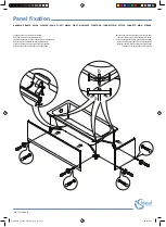
Page 31: ...32 34 2 mm 2 mm Pre installation ...

Page 32: ...33 34 Pre installation Pre installation completed Apply sealant according to local regulations ...

Page 33: ...C E R T I F I E D S PA C E T E C H N O L O G Y ...

Reviews: